1.2: Forces
- Page ID
- 50569

\( \newcommand{\vecs}[1]{\overset { \scriptstyle \rightharpoonup} {\mathbf{#1}} } \)
\( \newcommand{\vecd}[1]{\overset{-\!-\!\rightharpoonup}{\vphantom{a}\smash {#1}}} \)
\( \newcommand{\id}{\mathrm{id}}\) \( \newcommand{\Span}{\mathrm{span}}\)
( \newcommand{\kernel}{\mathrm{null}\,}\) \( \newcommand{\range}{\mathrm{range}\,}\)
\( \newcommand{\RealPart}{\mathrm{Re}}\) \( \newcommand{\ImaginaryPart}{\mathrm{Im}}\)
\( \newcommand{\Argument}{\mathrm{Arg}}\) \( \newcommand{\norm}[1]{\| #1 \|}\)
\( \newcommand{\inner}[2]{\langle #1, #2 \rangle}\)
\( \newcommand{\Span}{\mathrm{span}}\)
\( \newcommand{\id}{\mathrm{id}}\)
\( \newcommand{\Span}{\mathrm{span}}\)
\( \newcommand{\kernel}{\mathrm{null}\,}\)
\( \newcommand{\range}{\mathrm{range}\,}\)
\( \newcommand{\RealPart}{\mathrm{Re}}\)
\( \newcommand{\ImaginaryPart}{\mathrm{Im}}\)
\( \newcommand{\Argument}{\mathrm{Arg}}\)
\( \newcommand{\norm}[1]{\| #1 \|}\)
\( \newcommand{\inner}[2]{\langle #1, #2 \rangle}\)
\( \newcommand{\Span}{\mathrm{span}}\) \( \newcommand{\AA}{\unicode[.8,0]{x212B}}\)
\( \newcommand{\vectorA}[1]{\vec{#1}} % arrow\)
\( \newcommand{\vectorAt}[1]{\vec{\text{#1}}} % arrow\)
\( \newcommand{\vectorB}[1]{\overset { \scriptstyle \rightharpoonup} {\mathbf{#1}} } \)
\( \newcommand{\vectorC}[1]{\textbf{#1}} \)
\( \newcommand{\vectorD}[1]{\overrightarrow{#1}} \)
\( \newcommand{\vectorDt}[1]{\overrightarrow{\text{#1}}} \)
\( \newcommand{\vectE}[1]{\overset{-\!-\!\rightharpoonup}{\vphantom{a}\smash{\mathbf {#1}}}} \)
\( \newcommand{\vecs}[1]{\overset { \scriptstyle \rightharpoonup} {\mathbf{#1}} } \)
\( \newcommand{\vecd}[1]{\overset{-\!-\!\rightharpoonup}{\vphantom{a}\smash {#1}}} \)
\(\newcommand{\avec}{\mathbf a}\) \(\newcommand{\bvec}{\mathbf b}\) \(\newcommand{\cvec}{\mathbf c}\) \(\newcommand{\dvec}{\mathbf d}\) \(\newcommand{\dtil}{\widetilde{\mathbf d}}\) \(\newcommand{\evec}{\mathbf e}\) \(\newcommand{\fvec}{\mathbf f}\) \(\newcommand{\nvec}{\mathbf n}\) \(\newcommand{\pvec}{\mathbf p}\) \(\newcommand{\qvec}{\mathbf q}\) \(\newcommand{\svec}{\mathbf s}\) \(\newcommand{\tvec}{\mathbf t}\) \(\newcommand{\uvec}{\mathbf u}\) \(\newcommand{\vvec}{\mathbf v}\) \(\newcommand{\wvec}{\mathbf w}\) \(\newcommand{\xvec}{\mathbf x}\) \(\newcommand{\yvec}{\mathbf y}\) \(\newcommand{\zvec}{\mathbf z}\) \(\newcommand{\rvec}{\mathbf r}\) \(\newcommand{\mvec}{\mathbf m}\) \(\newcommand{\zerovec}{\mathbf 0}\) \(\newcommand{\onevec}{\mathbf 1}\) \(\newcommand{\real}{\mathbb R}\) \(\newcommand{\twovec}[2]{\left[\begin{array}{r}#1 \\ #2 \end{array}\right]}\) \(\newcommand{\ctwovec}[2]{\left[\begin{array}{c}#1 \\ #2 \end{array}\right]}\) \(\newcommand{\threevec}[3]{\left[\begin{array}{r}#1 \\ #2 \\ #3 \end{array}\right]}\) \(\newcommand{\cthreevec}[3]{\left[\begin{array}{c}#1 \\ #2 \\ #3 \end{array}\right]}\) \(\newcommand{\fourvec}[4]{\left[\begin{array}{r}#1 \\ #2 \\ #3 \\ #4 \end{array}\right]}\) \(\newcommand{\cfourvec}[4]{\left[\begin{array}{c}#1 \\ #2 \\ #3 \\ #4 \end{array}\right]}\) \(\newcommand{\fivevec}[5]{\left[\begin{array}{r}#1 \\ #2 \\ #3 \\ #4 \\ #5 \\ \end{array}\right]}\) \(\newcommand{\cfivevec}[5]{\left[\begin{array}{c}#1 \\ #2 \\ #3 \\ #4 \\ #5 \\ \end{array}\right]}\) \(\newcommand{\mattwo}[4]{\left[\begin{array}{rr}#1 \amp #2 \\ #3 \amp #4 \\ \end{array}\right]}\) \(\newcommand{\laspan}[1]{\text{Span}\{#1\}}\) \(\newcommand{\bcal}{\cal B}\) \(\newcommand{\ccal}{\cal C}\) \(\newcommand{\scal}{\cal S}\) \(\newcommand{\wcal}{\cal W}\) \(\newcommand{\ecal}{\cal E}\) \(\newcommand{\coords}[2]{\left\{#1\right\}_{#2}}\) \(\newcommand{\gray}[1]{\color{gray}{#1}}\) \(\newcommand{\lgray}[1]{\color{lightgray}{#1}}\) \(\newcommand{\rank}{\operatorname{rank}}\) \(\newcommand{\row}{\text{Row}}\) \(\newcommand{\col}{\text{Col}}\) \(\renewcommand{\row}{\text{Row}}\) \(\newcommand{\nul}{\text{Nul}}\) \(\newcommand{\var}{\text{Var}}\) \(\newcommand{\corr}{\text{corr}}\) \(\newcommand{\len}[1]{\left|#1\right|}\) \(\newcommand{\bbar}{\overline{\bvec}}\) \(\newcommand{\bhat}{\widehat{\bvec}}\) \(\newcommand{\bperp}{\bvec^\perp}\) \(\newcommand{\xhat}{\widehat{\xvec}}\) \(\newcommand{\vhat}{\widehat{\vvec}}\) \(\newcommand{\uhat}{\widehat{\uvec}}\) \(\newcommand{\what}{\widehat{\wvec}}\) \(\newcommand{\Sighat}{\widehat{\Sigma}}\) \(\newcommand{\lt}{<}\) \(\newcommand{\gt}{>}\) \(\newcommand{\amp}{&}\) \(\definecolor{fillinmathshade}{gray}{0.9}\)A force is any influence that causes a body to accelerate. Forces on a body can also cause stress in that body, which can result in the body deforming or breaking. Though forces can come from a variety of sources, there are three distinguishing features to every force. These features are the magnitude of the force, the direction of the force, and the point of application of the force. Forces are often represented as vectors (as in the diagram to the right) and each of these features can be determined from a vector representation of the forces on the body.
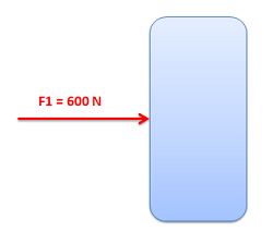
Magnitude:
The magnitude of a force is the degree to which the force will accelerate the body it is acting on; it is represented by a scalar (a single number). The magnitude can also be thought of as the strength of the force. When forces are represented as vectors, the magnitude of the force is usually explicitly labeled. The length of the vector also often corresponds to the relative magnitude of the vector, with longer vectors indicating larger magnitudes.
The magnitude of force is measured in units of mass times length over time squared. In metric units the most common unit is the Newton (N), where one Newton is one kilogram times one meter over one second squared. This means that a force of one Newton would cause a one-kilogram object to accelerate at a rate of one meter per second squared. In English units, the most common unit is the pound (lb), where one pound is equal to one slug times a foot over a second squared. This means that a one-pound force would cause an object with a mass of one slug to accelerate at a rate of one foot per second squared.
\[ Force \, = \, \frac{(mass)(distance)}{(time)^2} \]
\[ 1 \, \text{Newton} \, (N) \, = \, \frac{(kg)(m)}{s^2} \]
\[ 1 \, \text{pound} \, (lb) \, = \, \frac{(slug)(ft)}{s^2} \]
Direction:
In addition to having magnitudes, forces also have directions. As we said before, a force is any influence that causes a body to accelerate. Since acceleration has a specific direction, force also has a specific direction that matches this acceleration. The direction of the force is indicated in diagrams by the direction of the vector representing the force.
Direction has no units, but it is usually given by reporting angles between the vector representing the force and coordinate axes, or by reporting the X, Y, and Z components of the vector. Often times vectors that have the same direction as one of the coordinate axes will not have any angles or components listed. If this is true, it is usually safe to assume that the direction does match the direction of one of the coordinate axes.

Point of Application:
The point, or points, at which a force is applied to a body is important for understanding how the body will react. For particles, there is only a single point for the forces to act on, but for rigid bodies there are an infinite number of possible points of application. Some points of application will lead to the body undergoing simple linear acceleration; some will exert a moment on the body which will cause the body to undergo rotational acceleration as well as linear acceleration.
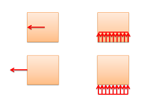
Depending on the nature of the point of application of a force, there are three general types of forces. These are point forces, surface forces, and body forces. Below is a diagram of a box being pulled by a rope across a frictionless surface. The box has three forces acting on it. The first is the force from the rope. This is a force applied to a single point on the box, and is therefore modeled as point force. Point forces are represented by a single vector. Second is the normal force from the ground that is supporting the box. Because this force is applied evenly to the bottom surface of the box, it is best modeled as a surface force. Surface forces are indicated by a number of vectors drawn side by side with a profile line to indicate the magnitude of the force at any point. The last force is the gravitational force pulling the box downward. Because this force is applied evenly to the entire volume of the box, it is best modeled as a body force. Body forces are sometimes shown as a field of vectors as shown, though they are often not drawn out at all because they end up cluttering the free body diagram.
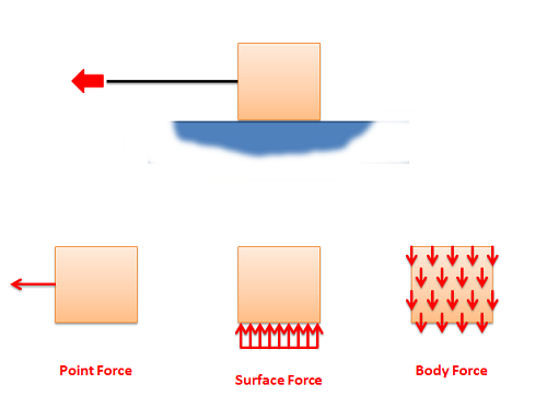
We will also sometimes talk about distributed forces. A distributed force is simply another name for either a surface or a body force.
The exact point or surface that the force is acting on can be drawn as either the head or the tail of the force vector in the free body diagram. Because of the principle of transmissibility, both options are known to represent the same physical system.