
1.4: Free Body Diagrams
- Page ID
- 51301

A free body diagram is a tool used to solve engineering mechanics problems. As the name suggests, the purpose of the diagram is to "free" the body from all other objects and surfaces around it so that it can be studied in isolation. We will also draw in any forces or moments acting on the body, including those forces and moments exerted by the surrounding bodies and surfaces that we removed.
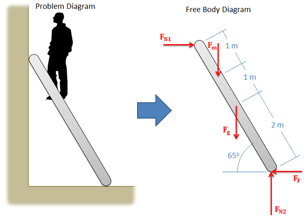
The diagram below shows a ladder supporting a person and the free body diagram of that ladder. As you can see, the ladder is separated from all other objects and all forces acting on the ladder are drawn in with the key dimensions and angles shown.
Constructing the Free Body Diagram:
The first step in solving most mechanics problems will be to construct a free body diagram. This simplified diagram will allow us to more easily write out the equilibrium equations for statics or strengths of materials problems, or the equations of motion for dynamics problems.
To construct the diagram we will use the following process:
- First draw the body being analyzed, separated from all other surrounding bodies and surfaces. Pay close attention to the boundary, identifying what is part of the body, and what is part of the surroundings.
- Second, draw in all external forces and moments acting directly on the body. Do not include any forces or moments that do not directly act on the body being analyzed. Do not include any forces that are internal to the body being analyzed.
- Once the forces are identified and added to the free body diagram, the last step is to label any key dimensions and angles on the diagram.
Some common types of forces seen in mechanics problems are:
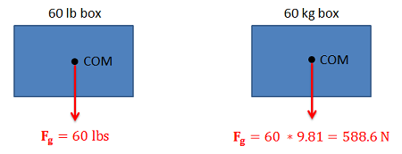
- Gravitational Forces: Unless otherwise noted, the mass of an object will result in a gravitational weight force applied to that body. This weight is usually given in pounds in the English system, and is modeled as 9.81 (\(g\)) times the mass of the body in kilograms for the metric system (resulting in a weight in Newtons). This force will always point down towards the center of the earth and act on the center of mass of the body.
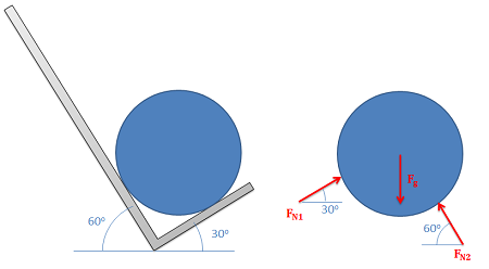
- Normal Forces (or Reaction Forces): Every object in direct contact with the body will exert a normal force on that body which prevents the two objects from occupying the same space at the same time. Note that only objects in direct contact can exert normal forces on the body.
- An object in contact with another object or surface will experience a normal force that is perpendicular (normal) to the surfaces in contact.
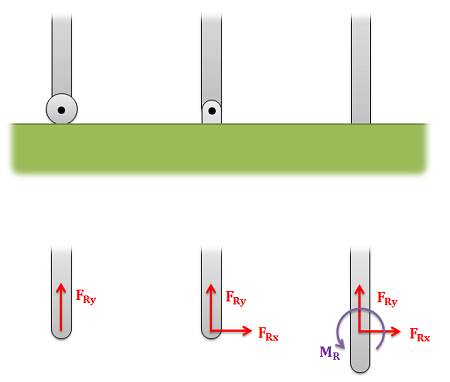
- Joints or connections between bodies can also cause reaction forces or moments, and we will have one force or moment for each type of motion or rotation the connection prevents.
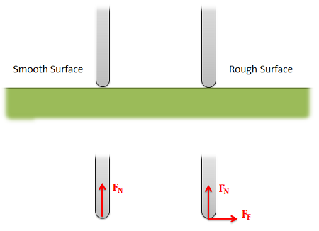
- Friction Forces: Objects in direct contact with the body can also exert friction forces, which will resist the two bodies sliding against one another, on the body. These forces will always be perpendicular to the surfaces in contact. Friction is the subject of an entire chapter in this book, but for simple scenarios we usually assume rough or smooth surfaces.
- For smooth surfaces we assume that there is no friction force.
- For rough surfaces we assume that the bodies will not slide relative to one another, no matter what. In this case, the friction force is always just large enough to prevent this sliding.
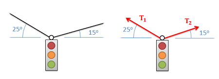
- Tension in Cables: Cables, wires or ropes attached to the body will exert a tension force on the body in the direction of the cable. These forces will always pull on the body, as ropes, cables and other flexible tethers cannot be used for pushing.
The above forces are the most common, but other forces such as pressure from fluids, spring forces and magnetic forces exist and may act on the body.
Worked Problems:
Example \(\PageIndex{1}\)
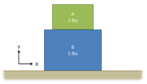
The drawing below shows two boxes sitting on a table. Draw a free body diagram of box A and box B.
- Solution
-
Video \(\PageIndex{2}\): Worked solution to example problem \(\PageIndex{1}\), provided by Dr. Jacob Moore. YouTube source: https://youtu.be/RMVa9kioALs.
Example \(\PageIndex{2}\)
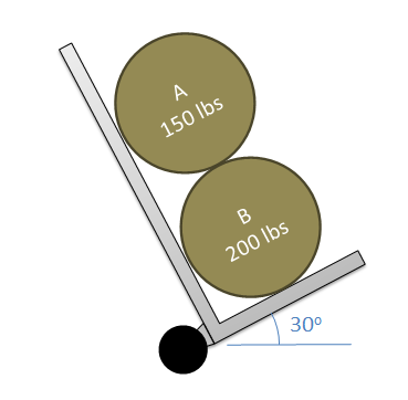
Two equally sized barrels are being transported in a handtruck as shown below. Draw a free body diagram of each of the two barrels.
- Solution
-
Video \(\PageIndex{3}\): Worked solution to example problem \(\PageIndex{2}\), provided by Dr. Jacob Moore. YouTube source: https://youtu.be/1a9gjFOIpK8.
Example \(\PageIndex{3}\)
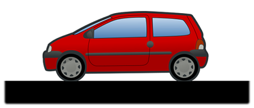
The car shown below is moving and then slams on the brakes locking up all four wheels. The distance between the two wheels is 8 feet and the center of mass is 3 feet behind and 2.5 feet above the point of contact between the front wheel and the ground. Draw a free body diagram of the car as it comes to a stop.
- Solution
-
Video \(\PageIndex{4}\): Worked solution to example problem \(\PageIndex{3}\), provided by Dr. Jacob Moore. YouTube source: https://youtu.be/GiB3_fSlJBA.
Example \(\PageIndex{4}\)
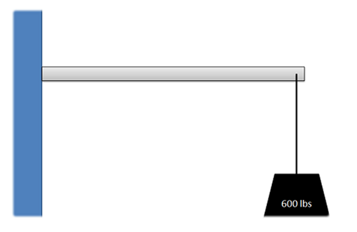
A 600-pound load is supported by a 5 meter long, 100-pound cantilever beam. Assume the beam is firmly anchored to the wall. Draw a free body diagram of the beam.
- Solution
Example \(\PageIndex{5}\)
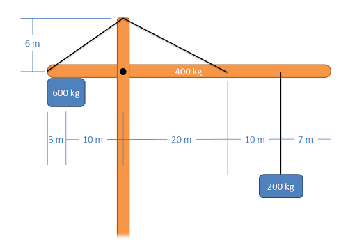
The main arm of a crane has a mass of 400 kg (assume the center of mass is at the midpoint of the arm), and supports a 200 kg load and a 600 kg counterweight. The arm is connected to the vertical support via a pin joint and two flexible cables. Draw a free body diagram of the arm.
- Solution
-
Video \(\PageIndex{6}\): Worked solution to example problem \(\PageIndex{5}\), provided by Dr. Jacob Moore. YouTube source: https://youtu.be/0V7ULRnnhmA.