
5.4: Method of Joints
- Page ID
- 52780

The method of joints is a process used to solve for the unknown forces acting on members of a truss. The method centers on the joints or connection points between the members, and it is usually the fastest and easiest way to solve for all the unknown forces in a truss structure.
Using the Method of Joints:
The process used in the method of joints is outlined below.
In the beginning, it is usually useful to label the members and the joints in your truss. This will help you keep everything organized and consistent in later analysis. In this book, the members will be labeled with letters and the joints will be labeled with numbers.
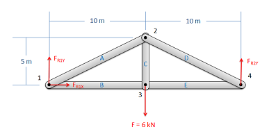
Treating the entire truss structure as a rigid body, draw a free body diagram, write out the equilibrium equations, and solve for the external reacting forces acting on the truss structure. This analysis should not differ from the analysis of a single rigid body.
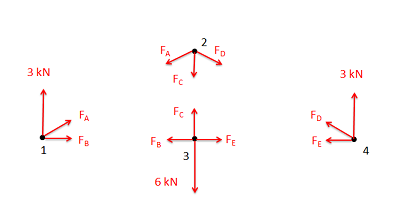
Assume there is a pin or some other small amount of material at each of the connection points between the members. Next you will draw a free body diagram for each connection point. Remember to include:
- Any external reaction or load forces that may be acting at that joint.
- A normal force for each two force member connected to that joint. Remember that for a two force member, the force will be acting along the line between the two connection points on the member. We will also need to guess if it will be a tensile or a compressive force. An incorrect guess now though will simply lead to a negative solution later on. A common strategy then is to assume all forces are tensile, then later in the solution any positive forces will be tensile forces and any negative forces will be compressive forces.
- Label each force in the diagram. Include any known magnitudes and directions and provide variable names for each unknown.
- Write out the equilibrium equations for each of the joints. You should treat the joints as particles, so there will be force equations but no moment equations. With either two (for 2D problems) or three (for 3D problems) equations for each joint; this should give you a large number of equations.
- In planar trusses, the sum of the forces in the \(x\) direction will be zero and the sum of the forces in the \(y\) direction will be zero for each of the joints. \[ \sum \vec{F} = 0 \] \[ \sum F_x = 0 \, ; \,\,\, \sum F_y = 0 \]
- In space trusses, the sum of the forces in the \(x\) direction will be zero, the sum of the forces in the \(y\) direction will be zero, and the sum of forces in the \(z\) direction will be zero for each of the joints. \[ \sum \vec{F} = 0 \] \[ \sum F_x = 0 \, ; \,\,\, \sum F_y = 0 \, ; \,\,\, \sum F_z = 0 \]
- Finally, solve the equilibrium equations for the unknowns. You can do this algebraically, solving for one variable at a time, or you can use matrix equations to solve for everything at once. If you assumed that all forces were tensile earlier, remember that negative answers indicate compressive forces in the members.
Example \(\PageIndex{1}\)
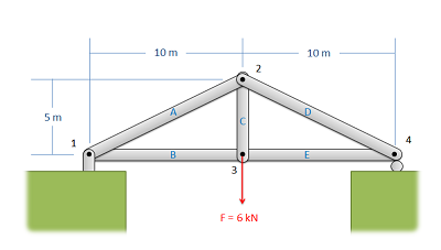
Find the force acting in each of the members in the truss bridge shown below. Remember to specify if each member is in tension or compression.
- Solution
-
Video \(\PageIndex{2}\): Worked solution to example problem \(\PageIndex{1}\), provided by Dr. Jacob Moore. YouTube source: https://youtu.be/vowewkEdTzw.
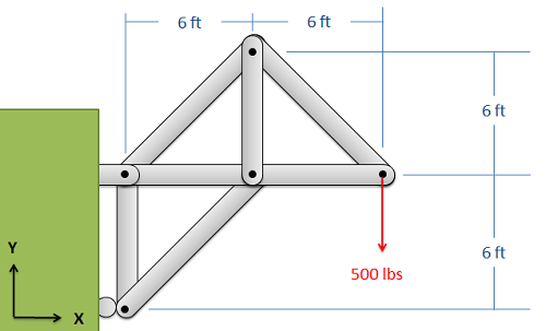
Example \(\PageIndex{2}\)
Find the force acting in each of the members of the truss shown below. Remember to specify if each member is in tension or compression.
- Solution
-
Video \(\PageIndex{3}\): Worked solution to example problem \(\PageIndex{2}\), provided by Dr. Jacob Moore. YouTube source: https://youtu.be/IxnClZ-ppjM.
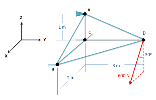
Example \(\PageIndex{3}\)
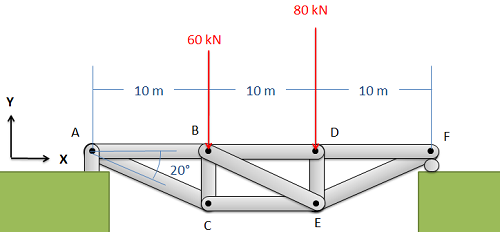
Find the force acting in each of the members of the truss shown below. Remember to specify if each member is in tension or compression.
- Solution
-
Video \(\PageIndex{4}\): Worked solution to example problem \(\PageIndex{3}\), provided by Dr. Jacob Moore. YouTube source: https://youtu.be/sDKESSbufEk.