
16.1: Vectors
- Page ID
- 55331

\( \newcommand{\vecs}[1]{\overset { \scriptstyle \rightharpoonup} {\mathbf{#1}} } \)
\( \newcommand{\vecd}[1]{\overset{-\!-\!\rightharpoonup}{\vphantom{a}\smash {#1}}} \)
\( \newcommand{\dsum}{\displaystyle\sum\limits} \)
\( \newcommand{\dint}{\displaystyle\int\limits} \)
\( \newcommand{\dlim}{\displaystyle\lim\limits} \)
\( \newcommand{\id}{\mathrm{id}}\) \( \newcommand{\Span}{\mathrm{span}}\)
( \newcommand{\kernel}{\mathrm{null}\,}\) \( \newcommand{\range}{\mathrm{range}\,}\)
\( \newcommand{\RealPart}{\mathrm{Re}}\) \( \newcommand{\ImaginaryPart}{\mathrm{Im}}\)
\( \newcommand{\Argument}{\mathrm{Arg}}\) \( \newcommand{\norm}[1]{\| #1 \|}\)
\( \newcommand{\inner}[2]{\langle #1, #2 \rangle}\)
\( \newcommand{\Span}{\mathrm{span}}\)
\( \newcommand{\id}{\mathrm{id}}\)
\( \newcommand{\Span}{\mathrm{span}}\)
\( \newcommand{\kernel}{\mathrm{null}\,}\)
\( \newcommand{\range}{\mathrm{range}\,}\)
\( \newcommand{\RealPart}{\mathrm{Re}}\)
\( \newcommand{\ImaginaryPart}{\mathrm{Im}}\)
\( \newcommand{\Argument}{\mathrm{Arg}}\)
\( \newcommand{\norm}[1]{\| #1 \|}\)
\( \newcommand{\inner}[2]{\langle #1, #2 \rangle}\)
\( \newcommand{\Span}{\mathrm{span}}\) \( \newcommand{\AA}{\unicode[.8,0]{x212B}}\)
\( \newcommand{\vectorA}[1]{\vec{#1}} % arrow\)
\( \newcommand{\vectorAt}[1]{\vec{\text{#1}}} % arrow\)
\( \newcommand{\vectorB}[1]{\overset { \scriptstyle \rightharpoonup} {\mathbf{#1}} } \)
\( \newcommand{\vectorC}[1]{\textbf{#1}} \)
\( \newcommand{\vectorD}[1]{\overrightarrow{#1}} \)
\( \newcommand{\vectorDt}[1]{\overrightarrow{\text{#1}}} \)
\( \newcommand{\vectE}[1]{\overset{-\!-\!\rightharpoonup}{\vphantom{a}\smash{\mathbf {#1}}}} \)
\( \newcommand{\vecs}[1]{\overset { \scriptstyle \rightharpoonup} {\mathbf{#1}} } \)
\(\newcommand{\longvect}{\overrightarrow}\)
\( \newcommand{\vecd}[1]{\overset{-\!-\!\rightharpoonup}{\vphantom{a}\smash {#1}}} \)
\(\newcommand{\avec}{\mathbf a}\) \(\newcommand{\bvec}{\mathbf b}\) \(\newcommand{\cvec}{\mathbf c}\) \(\newcommand{\dvec}{\mathbf d}\) \(\newcommand{\dtil}{\widetilde{\mathbf d}}\) \(\newcommand{\evec}{\mathbf e}\) \(\newcommand{\fvec}{\mathbf f}\) \(\newcommand{\nvec}{\mathbf n}\) \(\newcommand{\pvec}{\mathbf p}\) \(\newcommand{\qvec}{\mathbf q}\) \(\newcommand{\svec}{\mathbf s}\) \(\newcommand{\tvec}{\mathbf t}\) \(\newcommand{\uvec}{\mathbf u}\) \(\newcommand{\vvec}{\mathbf v}\) \(\newcommand{\wvec}{\mathbf w}\) \(\newcommand{\xvec}{\mathbf x}\) \(\newcommand{\yvec}{\mathbf y}\) \(\newcommand{\zvec}{\mathbf z}\) \(\newcommand{\rvec}{\mathbf r}\) \(\newcommand{\mvec}{\mathbf m}\) \(\newcommand{\zerovec}{\mathbf 0}\) \(\newcommand{\onevec}{\mathbf 1}\) \(\newcommand{\real}{\mathbb R}\) \(\newcommand{\twovec}[2]{\left[\begin{array}{r}#1 \\ #2 \end{array}\right]}\) \(\newcommand{\ctwovec}[2]{\left[\begin{array}{c}#1 \\ #2 \end{array}\right]}\) \(\newcommand{\threevec}[3]{\left[\begin{array}{r}#1 \\ #2 \\ #3 \end{array}\right]}\) \(\newcommand{\cthreevec}[3]{\left[\begin{array}{c}#1 \\ #2 \\ #3 \end{array}\right]}\) \(\newcommand{\fourvec}[4]{\left[\begin{array}{r}#1 \\ #2 \\ #3 \\ #4 \end{array}\right]}\) \(\newcommand{\cfourvec}[4]{\left[\begin{array}{c}#1 \\ #2 \\ #3 \\ #4 \end{array}\right]}\) \(\newcommand{\fivevec}[5]{\left[\begin{array}{r}#1 \\ #2 \\ #3 \\ #4 \\ #5 \\ \end{array}\right]}\) \(\newcommand{\cfivevec}[5]{\left[\begin{array}{c}#1 \\ #2 \\ #3 \\ #4 \\ #5 \\ \end{array}\right]}\) \(\newcommand{\mattwo}[4]{\left[\begin{array}{rr}#1 \amp #2 \\ #3 \amp #4 \\ \end{array}\right]}\) \(\newcommand{\laspan}[1]{\text{Span}\{#1\}}\) \(\newcommand{\bcal}{\cal B}\) \(\newcommand{\ccal}{\cal C}\) \(\newcommand{\scal}{\cal S}\) \(\newcommand{\wcal}{\cal W}\) \(\newcommand{\ecal}{\cal E}\) \(\newcommand{\coords}[2]{\left\{#1\right\}_{#2}}\) \(\newcommand{\gray}[1]{\color{gray}{#1}}\) \(\newcommand{\lgray}[1]{\color{lightgray}{#1}}\) \(\newcommand{\rank}{\operatorname{rank}}\) \(\newcommand{\row}{\text{Row}}\) \(\newcommand{\col}{\text{Col}}\) \(\renewcommand{\row}{\text{Row}}\) \(\newcommand{\nul}{\text{Nul}}\) \(\newcommand{\var}{\text{Var}}\) \(\newcommand{\corr}{\text{corr}}\) \(\newcommand{\len}[1]{\left|#1\right|}\) \(\newcommand{\bbar}{\overline{\bvec}}\) \(\newcommand{\bhat}{\widehat{\bvec}}\) \(\newcommand{\bperp}{\bvec^\perp}\) \(\newcommand{\xhat}{\widehat{\xvec}}\) \(\newcommand{\vhat}{\widehat{\vvec}}\) \(\newcommand{\uhat}{\widehat{\uvec}}\) \(\newcommand{\what}{\widehat{\wvec}}\) \(\newcommand{\Sighat}{\widehat{\Sigma}}\) \(\newcommand{\lt}{<}\) \(\newcommand{\gt}{>}\) \(\newcommand{\amp}{&}\) \(\definecolor{fillinmathshade}{gray}{0.9}\)Vectors are used in engineering mechanics to represent quantities that have both a magnitude and a direction. Many engineering quantities, such as forces, displacements, velocities, and accelerations, will need to be represented as vectors for analysis. Vector quantities contrast with scalar values (such as mass, area, or speed), which have a magnitude but no direction.
When dealing with vectors in equations, engineers commonly denote something as a vector by putting an arrow over the variable. Variables without an arrow over top of them represent a scalar quantity, or simply the magnitude of that vector quantity.
\begin{align} \text{Vector Quantity:} \quad &\, \vec{F} \\ \text{Scalar Quantity:} \quad &\, F \end{align}
In contrast with scalar quantities, we cannot add, subtract, multiply or divide them by simply adding, subtracting, multiplying or dividing the magnitudes. The directions will also play a critical role in solving equations that contain vector quantities.
Vector Representation:
To represent a vector quantity, we will generally have two options. These two options are:
- Magnitude and Direction Form: Where the magnitude is given as a single quantity and the direction is given via an angle or combination of angles.
- Component Form: Where the magnitude and direction are given through component magnitudes in each coordinate direction.
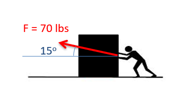
The magnitude and direction form of vector quantities are often used at the start and end of a problem. This is because it is often easier to measure things likes forces and velocities as a magnitude and direction at the start of a problem, and it is often easier to visualize the final result as a magnitude and direction at the end. Vectors represented as a magnitude and direction need to be shown visually through the use of an arrow, where the magnitude is the length of the arrow, and the direction is shown through the arrow head and an angle or angles relative to some known axes or other direction.
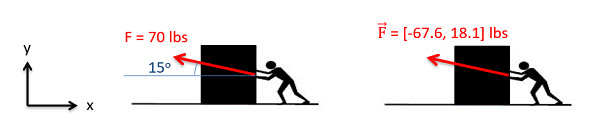
The component form of a vector is often used in middle of the problem because it is far easier to do math with vector quantities in component form. Vectors can be represented in component form in one of two ways. First we can use square brackets to indicate a vector, with the \(x\), \(y\), and possibly \(z\) components separated by commas. Alternatively, we can write out a vector in component form using the magnitudes in front of unit vectors to indicate directions (generally the \(\hat{i}\), \(\hat{j}\), and \(\hat{k}\) unit vectors for the \(x\), \(y\), and \(z\) directions respectively). Neither of these component forms relies on a visual depiction of the vector as with the magnitude and direction form, though it is important to clearly identify the coordinate system in earlier diagrams.
\begin{align} \text{With Brackets:} \quad &\, \vec{F} = [3,4,5] \\ \text{With Unit Vectors:} \quad &\, \vec{F} = 3 \hat{i} + 4 \hat{j} + 5 \hat{k} \end{align}
Converting Between Vector Representations in 2D
For our analysis, we will often find it advantageous to have the vectors in one form or the other, and will therefore need to convert the vector from a magnitude and direction to component form or vice versa. To do this we will use right triangles and trigonometry.
Going from a Magnitude and Direction to Component Form
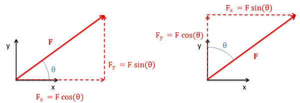
To go from a magnitude and direction to component form, we will first draw a right triangle with the hypotenuse being the original vector. The horizontal arm of the triangle will then be the \(x\)-component of the vector while the vertical arm is the \(y\) component of the vector. If we know the angle of the vector with respect to either the horizontal or the vertical, we can use the sine and cosine relationship to find the \(x\) and \(y\) components.
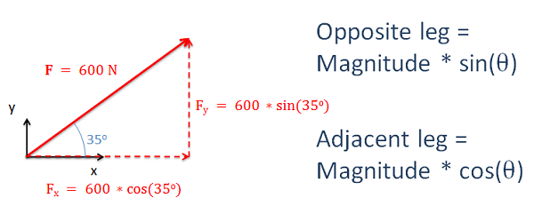
It is important to remember that how we measure the angle will affect the sine and cosine relationships. Multiplying the magnitude by the sine will always give us the opposite leg and multiplying the magnitude by the cosine will always give us the adjacent leg.
Going from Component Form to Magnitude and Direction
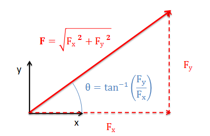
To find the magnitude and the direction of a vector using components, we will use the same process in reverse. We will draw the components as the legs of a right triangle, where the hypotenuse of the triangle shows the magnitude and direction of the vector.
To find the magnitude of the vector we will use the Pythagorean Theorem, taking the square root of the sum of the squares of each component. To find the angle, we can easily use the inverse tangent function, relating the opposite and adjacent legs of our right triangle.
If we know the magnitude of the hypotenuse, we can also use the inverse sine and cosine functions in place of the inverse tangent function to find the angle. As with the previous conversion, it is important to clearly identify the opposite leg, the adjacent leg, and the hypotenuse in our diagrams and to think of these when applying the inverse trig functions.
Converting Between Vector Representations in 3D
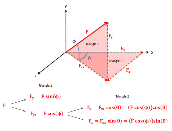
In three dimensions, we will have either three components (\(x\), \(y\), and \(z\)) for component form or a magnitude and two angles for the direction in magnitude and direction form. To convert between forms we will need to draw in two sets of right triangles. The hypotenuse of the first triangle will be the original vector and one of the legs will be one of the three components. The other leg will then be the hypotenuse of the second triangle. The legs of this second triangle will then be the remaining two components as shown in the diagram below. Use sine and cosine relationships to find the magnitude of each component along the way. This general process of two consecutive right triangles will always hold true, but depending on angles that are given or chosen which components end up being which leg can vary. Carefully plotting everything out in a diagram is important for this reason.
To go from component form back to a magnitude and direction, we will use the 3D form of the Pythagorean Theorem (the magnitude will be the square root of the sum of the three components squared) and we can again use the inverse trig functions to find the angles. We simply need to work backwards through the two right triangles in our problem, so again it is important to carefully draw out your diagrams.
Alternative Method for Finding 3D Vector Components
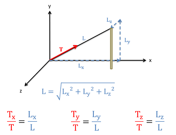
Sometimes, as with the tension in a cable, the geometry of the cable is given in component form rather than as angles. In cases such as this we could use geometry to figure out the angles and then use those angles to figure out the components, but there is a mathematical shortcut that will allow us to solve for the components more quickly involving the ratio of lengths. Specifically, the ratios of the components of the cable length to the overall length of the cable will be the same as the ratio of the corresponding force components to the overall magnitude of the force.
To use this method we will first need to find the overall length of the cable (or other physical geometric feature) using the Pythagorean Theorem. Once we have that overall length, we find a ratio by taking the x component of the length divided by the overall length. To find the \(x\)-component of the force, we simply multiply the overall magnitude of the force by this ratio of lengths (\(L_x/L\)). The process for the \(y\) and \(z\) components follows a similar path, except the ratios would include the \(y\) and \(z\) component lengths instead of the \(x\) component.
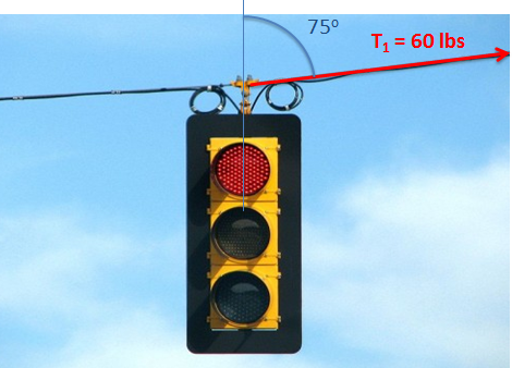
Example \(\PageIndex{1}\)
Determine the \(x\) and \(y\) components of the vector shown below.
- Solution:
-
Video \(\PageIndex{2}\): Worked solution to example problem \(\PageIndex{1}\), provided by Dr. Jacob Moore. YouTube source: https://youtu.be/TRS6jiih96o.
Example \(\PageIndex{2}\)
Determine the \(x\) and \(y\) components of the vector shown below.
- Solution:
-
Video \(\PageIndex{3}\): Worked solution to example problem \(\PageIndex{2}\), provided by Dr. Jacob Moore. YouTube source: https://youtu.be/hUrlI6eLGvE.
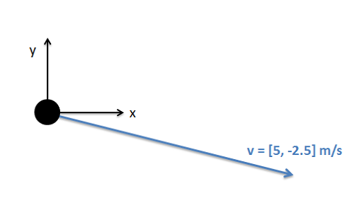
Example \(\PageIndex{3}\)
The velocity vector of the hockey puck shown below is given in component form. Determine the magnitude and direction of the velocity with respect to the axes given.
- Solution:
-
Video \(\PageIndex{4}\): Worked solution to example problem \(\PageIndex{3}\), provided by Dr. Jacob Moore. YouTube source: https://youtu.be/3GeIU3Fc_qA.
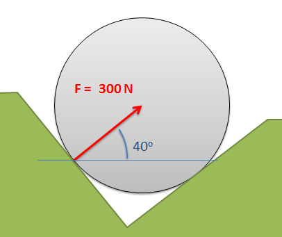
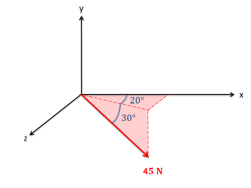
Example \(\PageIndex{4}\)
Determine the \(x\), \(y\), and \(z\) components of the force vector shown below.
- Solution:
-
Video \(\PageIndex{5}\): Worked solution to example problem \(\PageIndex{4}\), provided by Dr. Jacob Moore. YouTube source: https://youtu.be/ZG31PoIfIEc.
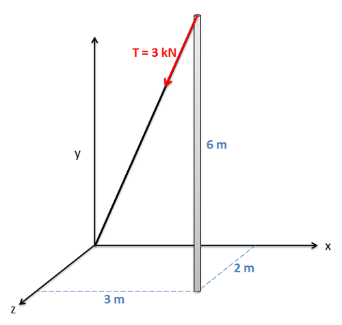
Example \(\PageIndex{5}\)
A cable as shown below is used to tether the top of a pole to a point on the ground. The cable has a tension force of 3 kN that acts along the direction of the cable as shown below. What are the \(x\), \(y\), and \(z\) components of the tension force acting on the top of the pole?
- Solution:
-
Video \(\PageIndex{6}\): Worked solution to example problem \(\PageIndex{5}\), provided by Dr. Jacob Moore. YouTube source: https://youtu.be/dUJwBohfCTU.