
Organic Solar Cells
- Page ID
- 352
\( \newcommand{\vecs}[1]{\overset { \scriptstyle \rightharpoonup} {\mathbf{#1}} } \)
\( \newcommand{\vecd}[1]{\overset{-\!-\!\rightharpoonup}{\vphantom{a}\smash {#1}}} \)
\( \newcommand{\dsum}{\displaystyle\sum\limits} \)
\( \newcommand{\dint}{\displaystyle\int\limits} \)
\( \newcommand{\dlim}{\displaystyle\lim\limits} \)
\( \newcommand{\id}{\mathrm{id}}\) \( \newcommand{\Span}{\mathrm{span}}\)
( \newcommand{\kernel}{\mathrm{null}\,}\) \( \newcommand{\range}{\mathrm{range}\,}\)
\( \newcommand{\RealPart}{\mathrm{Re}}\) \( \newcommand{\ImaginaryPart}{\mathrm{Im}}\)
\( \newcommand{\Argument}{\mathrm{Arg}}\) \( \newcommand{\norm}[1]{\| #1 \|}\)
\( \newcommand{\inner}[2]{\langle #1, #2 \rangle}\)
\( \newcommand{\Span}{\mathrm{span}}\)
\( \newcommand{\id}{\mathrm{id}}\)
\( \newcommand{\Span}{\mathrm{span}}\)
\( \newcommand{\kernel}{\mathrm{null}\,}\)
\( \newcommand{\range}{\mathrm{range}\,}\)
\( \newcommand{\RealPart}{\mathrm{Re}}\)
\( \newcommand{\ImaginaryPart}{\mathrm{Im}}\)
\( \newcommand{\Argument}{\mathrm{Arg}}\)
\( \newcommand{\norm}[1]{\| #1 \|}\)
\( \newcommand{\inner}[2]{\langle #1, #2 \rangle}\)
\( \newcommand{\Span}{\mathrm{span}}\) \( \newcommand{\AA}{\unicode[.8,0]{x212B}}\)
\( \newcommand{\vectorA}[1]{\vec{#1}} % arrow\)
\( \newcommand{\vectorAt}[1]{\vec{\text{#1}}} % arrow\)
\( \newcommand{\vectorB}[1]{\overset { \scriptstyle \rightharpoonup} {\mathbf{#1}} } \)
\( \newcommand{\vectorC}[1]{\textbf{#1}} \)
\( \newcommand{\vectorD}[1]{\overrightarrow{#1}} \)
\( \newcommand{\vectorDt}[1]{\overrightarrow{\text{#1}}} \)
\( \newcommand{\vectE}[1]{\overset{-\!-\!\rightharpoonup}{\vphantom{a}\smash{\mathbf {#1}}}} \)
\( \newcommand{\vecs}[1]{\overset { \scriptstyle \rightharpoonup} {\mathbf{#1}} } \)
\(\newcommand{\longvect}{\overrightarrow}\)
\( \newcommand{\vecd}[1]{\overset{-\!-\!\rightharpoonup}{\vphantom{a}\smash {#1}}} \)
\(\newcommand{\avec}{\mathbf a}\) \(\newcommand{\bvec}{\mathbf b}\) \(\newcommand{\cvec}{\mathbf c}\) \(\newcommand{\dvec}{\mathbf d}\) \(\newcommand{\dtil}{\widetilde{\mathbf d}}\) \(\newcommand{\evec}{\mathbf e}\) \(\newcommand{\fvec}{\mathbf f}\) \(\newcommand{\nvec}{\mathbf n}\) \(\newcommand{\pvec}{\mathbf p}\) \(\newcommand{\qvec}{\mathbf q}\) \(\newcommand{\svec}{\mathbf s}\) \(\newcommand{\tvec}{\mathbf t}\) \(\newcommand{\uvec}{\mathbf u}\) \(\newcommand{\vvec}{\mathbf v}\) \(\newcommand{\wvec}{\mathbf w}\) \(\newcommand{\xvec}{\mathbf x}\) \(\newcommand{\yvec}{\mathbf y}\) \(\newcommand{\zvec}{\mathbf z}\) \(\newcommand{\rvec}{\mathbf r}\) \(\newcommand{\mvec}{\mathbf m}\) \(\newcommand{\zerovec}{\mathbf 0}\) \(\newcommand{\onevec}{\mathbf 1}\) \(\newcommand{\real}{\mathbb R}\) \(\newcommand{\twovec}[2]{\left[\begin{array}{r}#1 \\ #2 \end{array}\right]}\) \(\newcommand{\ctwovec}[2]{\left[\begin{array}{c}#1 \\ #2 \end{array}\right]}\) \(\newcommand{\threevec}[3]{\left[\begin{array}{r}#1 \\ #2 \\ #3 \end{array}\right]}\) \(\newcommand{\cthreevec}[3]{\left[\begin{array}{c}#1 \\ #2 \\ #3 \end{array}\right]}\) \(\newcommand{\fourvec}[4]{\left[\begin{array}{r}#1 \\ #2 \\ #3 \\ #4 \end{array}\right]}\) \(\newcommand{\cfourvec}[4]{\left[\begin{array}{c}#1 \\ #2 \\ #3 \\ #4 \end{array}\right]}\) \(\newcommand{\fivevec}[5]{\left[\begin{array}{r}#1 \\ #2 \\ #3 \\ #4 \\ #5 \\ \end{array}\right]}\) \(\newcommand{\cfivevec}[5]{\left[\begin{array}{c}#1 \\ #2 \\ #3 \\ #4 \\ #5 \\ \end{array}\right]}\) \(\newcommand{\mattwo}[4]{\left[\begin{array}{rr}#1 \amp #2 \\ #3 \amp #4 \\ \end{array}\right]}\) \(\newcommand{\laspan}[1]{\text{Span}\{#1\}}\) \(\newcommand{\bcal}{\cal B}\) \(\newcommand{\ccal}{\cal C}\) \(\newcommand{\scal}{\cal S}\) \(\newcommand{\wcal}{\cal W}\) \(\newcommand{\ecal}{\cal E}\) \(\newcommand{\coords}[2]{\left\{#1\right\}_{#2}}\) \(\newcommand{\gray}[1]{\color{gray}{#1}}\) \(\newcommand{\lgray}[1]{\color{lightgray}{#1}}\) \(\newcommand{\rank}{\operatorname{rank}}\) \(\newcommand{\row}{\text{Row}}\) \(\newcommand{\col}{\text{Col}}\) \(\renewcommand{\row}{\text{Row}}\) \(\newcommand{\nul}{\text{Nul}}\) \(\newcommand{\var}{\text{Var}}\) \(\newcommand{\corr}{\text{corr}}\) \(\newcommand{\len}[1]{\left|#1\right|}\) \(\newcommand{\bbar}{\overline{\bvec}}\) \(\newcommand{\bhat}{\widehat{\bvec}}\) \(\newcommand{\bperp}{\bvec^\perp}\) \(\newcommand{\xhat}{\widehat{\xvec}}\) \(\newcommand{\vhat}{\widehat{\vvec}}\) \(\newcommand{\uhat}{\widehat{\uvec}}\) \(\newcommand{\what}{\widehat{\wvec}}\) \(\newcommand{\Sighat}{\widehat{\Sigma}}\) \(\newcommand{\lt}{<}\) \(\newcommand{\gt}{>}\) \(\newcommand{\amp}{&}\) \(\definecolor{fillinmathshade}{gray}{0.9}\)Solar cells are devices that utilize the light energy of the sun and convert it into electrical energy, which is needed for powering any electronic device. While organic solar cells(OSC) have the same fundamental structure as traditional or inorganic solar cells(ISC), OSCs use polymers instead of semiconductors, such as silicon or gallium arsenide, which are used in ISCs. While the efficiencies of OSCs are still somewhat low in relation to other solar cells, their advantages, such as being light in weight, flexible, low in material and processing costs, failure resistant, and relatively environmentally friendly make them a worthy competitor of ISCs. Considering fossil fuels are limited and alternate forms of energy need to be considered, OSCs will play a major role in supplying power to people around the world.
Introduction
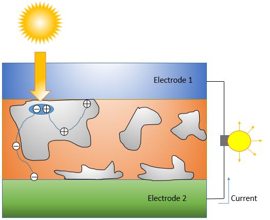
With an increasing demand for alternate energy, OSCs have been greatly explored and implemented. The functionality of OSCs is explained by the photovoltaic effect; photons become absorbed by the electron donor or acceptor layers and supply energy to the electron-hole pair. The excited electron-hole pair, or exciton, either returns to ground state, or it dissociates into an electron and hole due to the potential difference, which allows them to flow towards the cathode and anode respectively. The exact process of how electrons and holes travel through the medium is highly dependent on the type of junction used. The process of powering a light source with a dispersed heterojunction OSC is shown below in Figure 1.
Excitons are promoted to a higher energy level due to transfer of energy from photons emitted from the sun. The energy of a photon is related by \[E=h\nu=\frac{hc}{\lambda}\] where h is Planck's constant, ν is the frequency of the photon, c is the speed of light, and λ is the wavelength of the photon. It is important to realize that many of the photons emitted from the sun will not be absorbed in the solar cell, as photons can be absorbed by particles or molecules in the air, such as dust, oxygen, water, methane, or carbon dioxide[2]. Even on a clear, sunny day with minimal pollution in the air, solar cell surfaces must be cleaned in order to remove particulates to obtain maximum photon absorption. If too many particles, such as pollen or dust, accumulate on the surface of the solar cell, photons scatter instead of being absorbed, giving way to a much lower absorption.
While ISCs utilize the band gap of semiconductors, polymers in OSCs do not have band gaps. Instead, they function using the highest occupied molecular orbital(HOMO) and lowest unoccupied energy orbital(LUMO). For practical purposes, the HOMO and LUMO can be compared to the valence and conduction band of an ISCs respectively[1]. Since there is an energy difference between the HOMO and LUMO, this creates what is sometimes known as an organic band gap. The band gap energy of organic materials used in OSC is usually found to be within the 1-4eV range[1].
OSCs, while still not as efficient as ISCs, will continue to become more efficient as they are more heavily researched. Some significant advantages of OSCs are that they do not contain toxic heavy metals, making them easy to process and environmentally friendly, they are quite flexible, and they are very low in processing and material costs. In order to truly pursue the green movement, OSCs must be heavily implemented and researched, as they are the most environmentally and human friendly alternate energy source available today.
Single Layer OSC
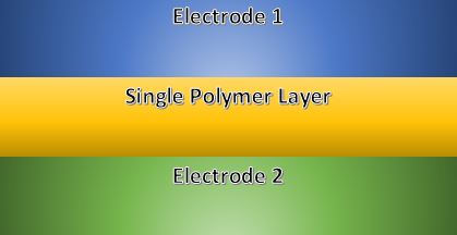
The most basic type of OSC is the single layer, as it is composed of a single polymer layer sandwiched in between two electrodes. Some types of materials used for the single polymer layer include phthalocyanine, polyflourenes, polypyrenes, and polythiophenes. Once photons become absorbed in the polymer layer, excitons are formed by promoting electrons into the LUMO. The potential difference created by the electrodes aids the separation process of the excitions by breaking the electrostatic bonds, allowing electrons to migrate to the cathode and holes to migrate the the anode. Unfortunately, single layer OSCs are highly inefficient, as the potential difference across the polymer is not strong enough to thoroughly break a significant amount of the excitons. Even when exciton bonds are broken, the energy to do so is typically just barely enough, which most often results in the electron and hole recombining[1]. Because of this phenomenon, not many of the electrons participate in the overall current needed to power a source.
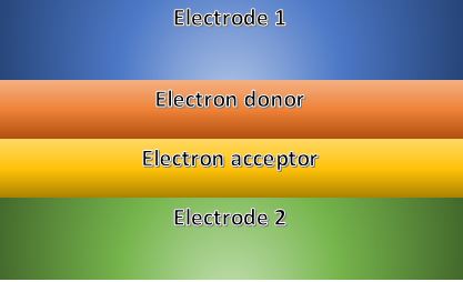
Dual Layer OSC
Dual layer OSCs are a significant upgrade to single layer, as an additional polymer layer is added between the electrodes. The two layers are classified as the electron donor and acceptor layer, which is shown in Figure 2.
The advantage of this style is that each of the two organic layers have a different electron affinity and ionization energy[1], meaning that additional force is generated at the donor-acceptor interface. Metals have loosely bound valence electrons, which makes it probable for them to lose an electron rather than gaining one, giving metals a low electron affinity. Other materials, such as non-metals, have their electrons much more tightly bound to the nucleus, meaning that they preferably gain electrons. Non-metals are known to have a high electron affinity for this reason. So, the electron donor and acceptor layers have a low and high electron affinity respectively.
This phenomenon is also explained using ionization energy; if only a small amount of energy is necessary for an electron to be removed from a material, the material is said to have a low ionization energy. So, the reason why metals, such as aluminum, are coupled with oxides, such as ITO, are coupled is because they encourage a flow of electrons in a particular direction.
While dual layer OSCs are more efficient than single layer, their efficiencies are still relatively unimpressive. Due to the interface between organic layers, excitons require more energy to cross the boundary and eventually reach the electrode. Also, in order to for the polymer layers to absorb an appropriate amount of photons, their thickness must be increased, or photons will be transmitted. Because photons can only supply excitons with a limited amount of energy, excitons rarely are able to travel to the electrode, as the interface and thick polymer layers do not allow for a long diffusion length.
Dispersed Heterojunction OSC
Dispersed heterojunction OSCs blend advantages of single layer with dual layer OSCs by removing the rough interface of dual layer by blending small pockets of electron donors and acceptors into a single layer, which is shown in Figure 4.
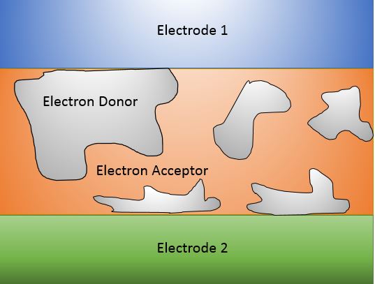
By introducing islands of electron donors in the electron acceptor region, the diffusion distance of the exciton is shortened, making it much more probable for electrons to reach the electrode. The diffusion distance the average electron before it recombines with a hole is roughly 3-10nm[1], which is roughly the distances attained between electron donor and acceptor regions. The donor and acceptor islands are very small in size, making their interface much smoother than dual layer OSCs. With both of these advantages, dispersed heterojunction OSCs are able to supply more electric current with the same amount of photon energy, making them more efficient.
Efficiencies
The overall efficiency of solar cells is broken down into several categories: conductive, charge carrier separation, thermodynamic, and reflective efficiencies. The efficiency relationship of any solar cell is given by \[\eta=\frac{P_{max}}{E*A}\]
where η is efficiency, Pmax is maximum power supplied to the solar cell, E is the input light, or irradiance, and A is the surface area of the solar cell. Solar cell efficiencies have been documented and published in a graph format by the National Renewable Energy Laboratory(NREL). The new maximum efficiency for organic solar cells was found to be 11.1%, but the highest efficiency of all types of solar cells was attained using a four-junction inorganic solar cell, which reached 44.7%[3].
Questions
1) Why is it necessary to use electrodes with different work functions? What is a good example of an electrode pair for an OSC?
2) When a photon strikes an electron-hole pair, it enters an excited state, known as an exciton. What are some of the outcomes of an excited exciton within a polymer layer?
3) Given the efficiency of a 4x4" OSC is .11, or 11%, determine the irradiance if power supplied is 300W.
Answers
1) When metals with high and low work functions are placed on each side of the organic material, they create a potential difference, which is what separates the exciton and the reason why electrons flow towards the positive electrode(cathode) and holes travel towards the negative electrode(anode). Examples of electrodes used are indium tin oxide(ITO) as the anode and metals such as aluminum, calcium, or magnesium for the cathode[1].
2) While it is ideal that the electrons travel to the cathode and holes travel to the anode after the exciton has split, this is not always the case. Other possibilities include recombination of the electron and hole(which releases energy), and geminate/non-geminate recombination in dispersed heterojuntion OSC[2]. Geminate is a term for electrons and holes that begin from the same exciton pair.
3) First convert 16 in2 to m2, then use the efficiency equation to solve. Answer: E=264 kW/m2
Additional Links
Wikipedia Pages
Conductive Polymer
Electron Affinity
Exciton
Organic Solar Cells
Photovoltaic Effect
Work Function
*All ChemWiki links dispersed through page*
References
[1] R. E. Hummel, Electronic Properties of Materials, 4th ed. New York: Springer, 2012.
[2] S. Ludwigs, A. Moule, D. Neher, and S.T. Turner, Advances in Polymer Science(Book 265), 2014 Ed. New York: Springer, 2014
[3] Best Research-Cell Efficiencies, (2014)National Renewable Energy Laboratory, [Online] Available here
[4] Z.H. Kafafi, Organic Electroluminescence, SPIE--The International Society for Optical Engineering (May 25, 2005)
[5] Z. Li and H. Meng, Organic Light-Emitting Materials and Devices, CRC Press; 1st ed. (September 12, 2006)
Contributors and Attributions
James Bellino
B.S. Materials Science and Engineering | June 2015
University of California, Davis
Department of Chemical Engineering and Materials Science