
13.6: Exercises
- Page ID
- 52982

\( \newcommand{\vecs}[1]{\overset { \scriptstyle \rightharpoonup} {\mathbf{#1}} } \)
\( \newcommand{\vecd}[1]{\overset{-\!-\!\rightharpoonup}{\vphantom{a}\smash {#1}}} \)
\( \newcommand{\dsum}{\displaystyle\sum\limits} \)
\( \newcommand{\dint}{\displaystyle\int\limits} \)
\( \newcommand{\dlim}{\displaystyle\lim\limits} \)
\( \newcommand{\id}{\mathrm{id}}\) \( \newcommand{\Span}{\mathrm{span}}\)
( \newcommand{\kernel}{\mathrm{null}\,}\) \( \newcommand{\range}{\mathrm{range}\,}\)
\( \newcommand{\RealPart}{\mathrm{Re}}\) \( \newcommand{\ImaginaryPart}{\mathrm{Im}}\)
\( \newcommand{\Argument}{\mathrm{Arg}}\) \( \newcommand{\norm}[1]{\| #1 \|}\)
\( \newcommand{\inner}[2]{\langle #1, #2 \rangle}\)
\( \newcommand{\Span}{\mathrm{span}}\)
\( \newcommand{\id}{\mathrm{id}}\)
\( \newcommand{\Span}{\mathrm{span}}\)
\( \newcommand{\kernel}{\mathrm{null}\,}\)
\( \newcommand{\range}{\mathrm{range}\,}\)
\( \newcommand{\RealPart}{\mathrm{Re}}\)
\( \newcommand{\ImaginaryPart}{\mathrm{Im}}\)
\( \newcommand{\Argument}{\mathrm{Arg}}\)
\( \newcommand{\norm}[1]{\| #1 \|}\)
\( \newcommand{\inner}[2]{\langle #1, #2 \rangle}\)
\( \newcommand{\Span}{\mathrm{span}}\) \( \newcommand{\AA}{\unicode[.8,0]{x212B}}\)
\( \newcommand{\vectorA}[1]{\vec{#1}} % arrow\)
\( \newcommand{\vectorAt}[1]{\vec{\text{#1}}} % arrow\)
\( \newcommand{\vectorB}[1]{\overset { \scriptstyle \rightharpoonup} {\mathbf{#1}} } \)
\( \newcommand{\vectorC}[1]{\textbf{#1}} \)
\( \newcommand{\vectorD}[1]{\overrightarrow{#1}} \)
\( \newcommand{\vectorDt}[1]{\overrightarrow{\text{#1}}} \)
\( \newcommand{\vectE}[1]{\overset{-\!-\!\rightharpoonup}{\vphantom{a}\smash{\mathbf {#1}}}} \)
\( \newcommand{\vecs}[1]{\overset { \scriptstyle \rightharpoonup} {\mathbf{#1}} } \)
\(\newcommand{\longvect}{\overrightarrow}\)
\( \newcommand{\vecd}[1]{\overset{-\!-\!\rightharpoonup}{\vphantom{a}\smash {#1}}} \)
\(\newcommand{\avec}{\mathbf a}\) \(\newcommand{\bvec}{\mathbf b}\) \(\newcommand{\cvec}{\mathbf c}\) \(\newcommand{\dvec}{\mathbf d}\) \(\newcommand{\dtil}{\widetilde{\mathbf d}}\) \(\newcommand{\evec}{\mathbf e}\) \(\newcommand{\fvec}{\mathbf f}\) \(\newcommand{\nvec}{\mathbf n}\) \(\newcommand{\pvec}{\mathbf p}\) \(\newcommand{\qvec}{\mathbf q}\) \(\newcommand{\svec}{\mathbf s}\) \(\newcommand{\tvec}{\mathbf t}\) \(\newcommand{\uvec}{\mathbf u}\) \(\newcommand{\vvec}{\mathbf v}\) \(\newcommand{\wvec}{\mathbf w}\) \(\newcommand{\xvec}{\mathbf x}\) \(\newcommand{\yvec}{\mathbf y}\) \(\newcommand{\zvec}{\mathbf z}\) \(\newcommand{\rvec}{\mathbf r}\) \(\newcommand{\mvec}{\mathbf m}\) \(\newcommand{\zerovec}{\mathbf 0}\) \(\newcommand{\onevec}{\mathbf 1}\) \(\newcommand{\real}{\mathbb R}\) \(\newcommand{\twovec}[2]{\left[\begin{array}{r}#1 \\ #2 \end{array}\right]}\) \(\newcommand{\ctwovec}[2]{\left[\begin{array}{c}#1 \\ #2 \end{array}\right]}\) \(\newcommand{\threevec}[3]{\left[\begin{array}{r}#1 \\ #2 \\ #3 \end{array}\right]}\) \(\newcommand{\cthreevec}[3]{\left[\begin{array}{c}#1 \\ #2 \\ #3 \end{array}\right]}\) \(\newcommand{\fourvec}[4]{\left[\begin{array}{r}#1 \\ #2 \\ #3 \\ #4 \end{array}\right]}\) \(\newcommand{\cfourvec}[4]{\left[\begin{array}{c}#1 \\ #2 \\ #3 \\ #4 \end{array}\right]}\) \(\newcommand{\fivevec}[5]{\left[\begin{array}{r}#1 \\ #2 \\ #3 \\ #4 \\ #5 \\ \end{array}\right]}\) \(\newcommand{\cfivevec}[5]{\left[\begin{array}{c}#1 \\ #2 \\ #3 \\ #4 \\ #5 \\ \end{array}\right]}\) \(\newcommand{\mattwo}[4]{\left[\begin{array}{rr}#1 \amp #2 \\ #3 \amp #4 \\ \end{array}\right]}\) \(\newcommand{\laspan}[1]{\text{Span}\{#1\}}\) \(\newcommand{\bcal}{\cal B}\) \(\newcommand{\ccal}{\cal C}\) \(\newcommand{\scal}{\cal S}\) \(\newcommand{\wcal}{\cal W}\) \(\newcommand{\ecal}{\cal E}\) \(\newcommand{\coords}[2]{\left\{#1\right\}_{#2}}\) \(\newcommand{\gray}[1]{\color{gray}{#1}}\) \(\newcommand{\lgray}[1]{\color{lightgray}{#1}}\) \(\newcommand{\rank}{\operatorname{rank}}\) \(\newcommand{\row}{\text{Row}}\) \(\newcommand{\col}{\text{Col}}\) \(\renewcommand{\row}{\text{Row}}\) \(\newcommand{\nul}{\text{Nul}}\) \(\newcommand{\var}{\text{Var}}\) \(\newcommand{\corr}{\text{corr}}\) \(\newcommand{\len}[1]{\left|#1\right|}\) \(\newcommand{\bbar}{\overline{\bvec}}\) \(\newcommand{\bhat}{\widehat{\bvec}}\) \(\newcommand{\bperp}{\bvec^\perp}\) \(\newcommand{\xhat}{\widehat{\xvec}}\) \(\newcommand{\vhat}{\widehat{\vvec}}\) \(\newcommand{\uhat}{\widehat{\uvec}}\) \(\newcommand{\what}{\widehat{\wvec}}\) \(\newcommand{\Sighat}{\widehat{\Sigma}}\) \(\newcommand{\lt}{<}\) \(\newcommand{\gt}{>}\) \(\newcommand{\amp}{&}\) \(\definecolor{fillinmathshade}{gray}{0.9}\)Analysis
1. For the circuit shown in Figure \(\PageIndex{1}\), determine apparent power \(S\), real power \(P\), reactive power \(Q\) and power factor \(PF\). Also, draw the power triangle.
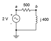
Figure \(\PageIndex{1}\)
2. For the circuit shown in Figure \(\PageIndex{2}\), determine apparent power \(S\), real power \(P\), reactive power \(Q\) and power factor \(PF\). Also, draw the power triangle.
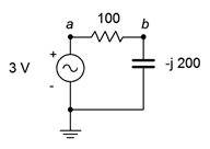
Figure \(\PageIndex{2}\)
3. For the circuit shown in Figure \(\PageIndex{3}\), determine apparent power \(S\), real power \(P\), reactive power \(Q\) and power factor \(PF\). Also, draw the power triangle. The source is 120 volts.
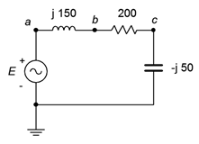
Figure \(\PageIndex{3}\)
4. For the circuit shown in Figure \(\PageIndex{4}\), determine apparent power \(S\), real power \(P\), reactive power \(Q\) and power factor \(PF\). Also, draw the power triangle. The source is 120 volts.
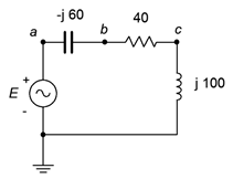
Figure \(\PageIndex{4}\)
5. For the circuit shown in Figure \(\PageIndex{5}\), determine apparent power \(S\), real power \(P\), reactive power \(Q\) and power factor \(PF\). The source is 90 volts, \(X_L = j30\) \(\Omega\), \(R\) = 50 \(\Omega\).
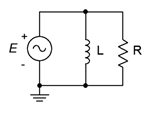
Figure \(\PageIndex{5}\)
6. For the circuit shown in Figure \(\PageIndex{6}\), determine apparent power \(S\), real power \(P\), reactive power \(Q\) and power factor \(PF\). Also, draw the power triangle. The source is 240 volts, \(X_C = −j200\) \(\Omega\), \(R\) = 75 \(\Omega\).
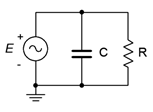
Figure \(\PageIndex{6}\)
7. For the circuit shown in Figure \(\PageIndex{7}\), determine apparent power \(S\), real power \(P\), reactive power \(Q\) and power factor \(PF\). The source is 120 volts, \(X_L = j40\) \(\Omega\), \(X_C = −j25\) \(\Omega\), \(R\) = 20 \(\Omega\).
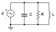
Figure \(\PageIndex{7}\)
8. For the circuit shown in Figure \(\PageIndex{7}\), determine apparent power \(S\), real power \(P\), reactive power \(Q\) and power factor \(PF\). The source is 120 volts, 60 Hz. \(R\) = 80 \(\Omega\), \(C\) = 20 \(\mu\)F, \(L\) = 400 mH.
9. An audio power amplifier delivers a 30 volt RMS 1 kHz sine to a loudspeaker. If the loudspeaker impedance at this frequency is \(7\angle 45^{\circ}\), determine the RMS current delivered to the load and the true power.
10. An audio power amplifier delivers an 80 volt peak 35 Hz sine to a subwoofer. If the subwoofer impedance at this frequency is \(4\angle −30^{\circ}\), determine the peak current delivered to the load and the true power.
11. A certain load is specified as drawing 8 kVA with a lagging power factor of 0.8. Determine the real power \(P\), and the reactive power \(Q\). Further, if the source is 120 volts at 60 Hz, determine the effective impedance of the load in both polar and rectangular form, and the requisite resistance/inductance/capacitance values.
12. A certain load is specified as drawing 20 kVA with a leading power factor of 0.9. Determine the real power \(P\), the reactive power \(Q\) and draw the power triangle. If the source is 240 volts at 60 Hz, determine the effective impedance of the load in both polar and rectangular form, and the requisite resistance/inductance/capacitance values.
13. Consider the system shown in Figure \(\PageIndex{8}\). \(E\) is a standard 120 V input. If the three loads are 45 W, 60 W and 75 W incandescent light bulbs, respectively, determine the apparent power delivered to the system, the source current, the reactive power and the real power.
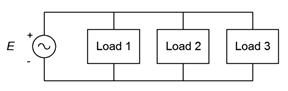
Figure \(\PageIndex{8}\)
14. Given the system shown in Figure \(\PageIndex{8}\), determine the apparent power delivered to the system, the source current, the real power, the reactive power and the efficiency. \(E\) is 120 V. The three loads are resistive heating elements of 500 W, 1200 W and 1500 W, respectively.
15. Consider the system shown in Figure \(\PageIndex{9}\). \(E\) is 240 V. If the three loads are 200 W, 400 W and 1000 W resistive, respectively, determine the apparent power delivered to the system, the real power and the reactive power.
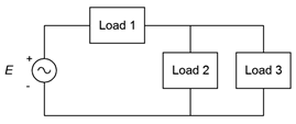
Figure \(\PageIndex{9}\)
16. Given the system shown in Figure \(\PageIndex{9}\), determine the apparent power delivered to the system, the real power, the reactive power and the efficiency. \(E\) is 480 V. The three loads are resistive heating elements of 1500 W, 2000 W and 3500 W, respectively.
17. Consider the system shown in Figure \(\PageIndex{8}\). \(E\) is 120 V. Load 1 is 1 kW resistive, load 2 is 400 W resistive and load 3 is 600 VAR inductive. Determine the apparent power delivered to the system, the source current, the reactive power, the real power and the power factor.
18. Consider the system shown in Figure \(\PageIndex{8}\). \(E\) is 240 V. Load 1 is 2 kW resistive, load 2 is 800 W resistive and load 3 is 1200 VAR capacitive. Determine the apparent power delivered to the system, the source current, the real power, the reactive power and the power factor.
19. Given the system shown in Figure \(\PageIndex{8}\), determine the apparent power delivered to the system, the source current, the real power, the reactive power and the power factor. \(E\) is 120 V. Load 1 is 600 W of incandescent lighting, load 2 is 1200 W of heating elements and load 3 is 200 VAR capacitive.
20. Given the system shown in Figure \(\PageIndex{8}\), determine the apparent power delivered to the system, the source current, the real power, the reactive power and the power factor. \(E\) is 60 V. Load 1 is 90 W of incandescent lighting, load 2 is 800 W of heating elements from a dryer and load 3 200 VAR inductive.
21. A 120 V 3 HP motor draws a real power of 2500 W from the source. Determine its efficiency.
22. A 120 V 12 HP motor draws a real power of 10 kW from the source. Determine its efficiency.
23. An ideal 120 V 2 HP motor draws an apparent power of 1800 W from the source. Determine its power factor.
24. An ideal 120 V 0.3 HP motor draws an apparent power of 270 W from the source. Determine its power factor.
25. A 120 V motor is rated at 0.5 HP. It has an efficiency of 78% and a lagging power factor of 0.7. Determine the apparent power drawn from the source (\(S\)), the real power (\(P\)), and the reactive power (\(Q\)) supplied. Also draw the power triangle and find the delivered current.
26. A motor is rated at 10 HP. It has an efficiency of 92% and a lagging power factor of 0.8. Determine the apparent power drawn from the source (\(S\)), the real power (\(P\)), and the reactive power (\(Q\)) supplied. Also draw the power triangle. Finally, determined the current drawn from the 120 V source.
27. Consider the system shown in Figure \(\PageIndex{8}\). \(E\) is 120 V. Load 1 is 1 kW resistive, load 2 is 400 W resistive and load 3 is a 1 HP motor that is 80% efficient and has a 0.85 lagging power factor. For the system, determine the apparent power delivered, the source current, the real power, the reactive power and the power factor.
28. Consider the system shown in Figure \(\PageIndex{8}\). \(E\) is 120 V. Load 1 is 2.5 kW resistive, load 2 is 500 VAR capacitive and load 3 is a 2 HP motor that is 85% efficient and has a 0.9 lagging power factor. For the system, determine the total power delivered, the source current, the apparent power, the real power and the power factor.
29. For the system shown in Figure \(\PageIndex{10}\), E is 240 V. Load 1 is 1.2 kW resistive heating, load 2 is 400 W resistive lighting, load 3 is a 0.5 HP motor that is 80% efficient with a 0.7 lagging power factor, and load 4 is a 1 HP motor that is 85% efficient with a 0.8 lagging power factor. For the system, determine the apparent power delivered, the source current, the real power, the reactive power and the power factor.
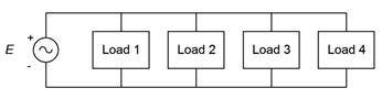
Figure \(\PageIndex{10}\)
Design
30. A 120 V 60 Hz source drives a load equivalent to a 75 \(\Omega\) resistor in parallel with a 25 \(\mu\)F capacitor. Determine the appropriate capacitance or inductance value to place across this load to produce unity power factor.
31. A 240 V 60 Hz source drives a load equivalent to a 10 \(\Omega\) resistor in parallel with a 50 mH inductor. Determine the appropriate capacitance or inductance value to place across this load to produce unity power factor.
32. A load of \(50\angle 30^{\circ}\) is driven by a 120 V 60 Hz source. Determine the appropriate capacitance or inductance value to place across this load to produce unity power factor.
33. A load of \(50\angle −50^{\circ}\) is driven by a 240 V 60 Hz source. Determine the appropriate capacitance or inductance value to place across this load to produce unity power factor.
34. A certain load is specified as drawing 8 kVA with a lagging power factor of 0.8. The source is 120 volts at 60 Hz. Determine the appropriate capacitor or inductor to place in parallel with this load to produce unity power factor.
35. A certain load is specified as drawing 20 kVA with a leading power factor of 0.9. The source is 240 volts at 60 Hz. Determine the appropriate capacitor or inductor to place in parallel with this load to produce unity power factor.
36. A 240 V 60 Hz source is connected to a load consisting of heating elements of 10 kW along with a 15 HP motor with \(\eta\) = 90%, \(PF\) = 0.85. Determine an appropriate capacitor or inductor to place in parallel to produce unity power factor.
37. A 120 V 60 Hz source is connected to a load consisting of 350 W of resistive lighting along with a 1.5 HP motor with \(\eta\) = 70%, \(PF\) = 0.75. Determine an appropriate component to place in parallel to produce unity power factor.
Challenge
38. A power distribution system for a concert has the following specifications: Ten class D audio power amplifiers rated at 2 kW output each with 90% efficiency and unity power factor, 10 kW worth of resistive stage lighting to illuminate the musicians alongside a troupe of trained dancing kangaroos, a 3 HP motor used to continuously rotate the drum riser throughout the performance (\(\eta\) = 80%, \(PF\) = 0.75) and a 2 HP compressor which inflates and deflates a giant rubber T. rex during particularly exciting parts of the show (\(\eta\) = 85%, \(PF\) = 0.8). For the system, determine the total power delivered, the source current, the apparent power, the real power, and the power factor. Finally, make a sketch of this extravaganza with its entertainers in full regalia singing their latest tune “Maximum Volume”.
Simulation
39. Verify the design of problem 28 by performing a transient analysis. The design will have been successful if the source current and voltage are in phase.
40. Verify the design of problem 29 by performing a transient analysis. The design will have been successful if the source current and voltage are in phase.