
4.3: 3-Address Instructions
- Page ID
- 76111

Most basic instructions in the ARM CPU are simple 3-address instructions and can be explained using the CPU in Figure 4.1. This will be done by covering a simple version of the move instruction (mov), followed by addition (ADD) and subtraction (SUB), multiplication (MUL), division (IDIV, UDIV), logical operations (AND, ORR, EOR, BIC, and MVN), and finally shift (LSL, LSR, ASR, and ROR) operations. Note that only the 3-address format of these instructions will be covered here. Other formats for these instructions will be covered in Section 4.3, or chapter 5.
4.3.1 MOV Instruction
To make programs interesting, there must be some data in the registers to operate on. This data comes either from memory, or the instruction that is executing. To use immediate data in the executing instruction, the MOV instruction is used. The MOV instruction allows numbers to be specified and moved into a register, or values in one register to be moved to another register.
There are two basic formats for the mov instruction: a MOV that moves an immediate value into a register and a MOV that moves a value from one register to another register. The first format of this move instruction using an immediate is:
MOV Rd, immediate
An example of using the immediate format of the mov instruction is:
MOV r1, #36
This instruction moves the value of decimal 36 into the register r1, or r1 ← 36. Note that the immediate value is an 8-bit number from decimal -128...127. This value can be specified using a decimal value (#36), a hex value (#0x24), or a binary value (#0b00100100).
The second format of the MOV instruction uses 2 registers. This format of the MOV command is:
MOV Rd, Rm
An example of using this register format of the mov instruction is:
MOV r1, r2
In this instruction, the value in register r2 is moved into register r1, or r1 ← r2.
4.3.2 ADD and SUB instructions
In this section, the add (ADD) and subtract (SUB) operators will be explained. These are 3- address instructions again with two formats: a register format and an immediate format.
The immediate format of these two instructions are:
   ADD Rd, Rn, immediate
   SUB Rd, Rn, immediate
An example of using the immediate format of the add and subtract instructions is:
   ADD r1, r2, #36
   SUB r1, r2, #36
In these instructions the value of 36 is added to or subtracted from the value in r2, and the result stored in r1. This corresponds to r1 ← r2 + 36 in the first instruction and r1 ← r2 - 36 in the second instruction.
The register format of these two instructions is:
    ADD Rd, Rn, Rm
    SUB Rd, Rn, Rm
An example of using the register format of the add and subtract instructions is:
    ADD r1, r2, r3
    SUB r1, r2, r3
For these instructions, the value of r3 is added to or subtracted from the value in r2 and the result stored in r1. This corresponds to r1 ← r2 + r3 in the first instruction and r1 ← r2 - r3 in the second instruction.
4.3.3 MUL, SDIV, and UDIV instructions
In this section, the multiply (MUL), signed division (SDIV), and unsigned division (UDIV) operations are explained. The assembly instructions appear to be similar to the ADD and SUB instructions, but there are a number of differences. First, the MUL operation will not have an immediate format. The reason the mul instruction does not have an immediate form is that if the program is multiplying or dividing by a constant, there is always a better way to implement the operation using shifts and adds. So, there is no utility to implementing an immediate form of the operations.
The second difference is that the sp (r13) and pc (r15) cannot be used in the multiply or divide instructions.
Finally, the inputs to the MUL instructions will be Rm and Rs, not Rn and Rm.
The register forms of these three instructions are:
    MUL Rd, Rm, Rs
    SDIV Rd, Rn, Rm
    UDIV Rd, Rn, Rm
An example of using the register format of the mul, udiv, and sdiv instructions is:
  MUL r1, r2, r3
  SDIV r1, r2, r3
  UDIV r1, r2, r3
For these instructions, the value of r3 is multiplied by or divided into the value in r2 and the result stored in r1. This corresponds to r1 ← r2 * r3 in the first instruction and r1 ← r2 / r3 in the second and third instruction.
4.3.4 Division on a Raspberry Pi
Because of the amount of circuitry involved, some ARM chips did not implement division in hardware. My current Pi-0 and Pi-4 do not implement the divide instructions. Instead, the function __aeabi_idiv is used to do division. If you are using a CPU that does not implement division, use the following code fragment. The __aeabi_idiv function does integer division. The input dividend is in r0 and the divisor is in r1. The quotient, which is the return value of the function, is in r0.
MOV r0, #12
 MOV r1, #3
 BL __aeabi_idiv
 # The quotient 4 is in r0
7 Division on a Pi Zero
4.3.5 Logical Operations: AND, OR, XOR, and BIC
There are four logical operations in ARM assembly: AND (AND), OR (ORR), XOR (EOR), and Bit Clear (BIC). Also, included in this section is the move negative (MVN), which can be used to negate the value in a register and thus be considered a NOT operation.
To begin the discussion of these instructions, the definition of a logical operation will be covered. In a HLL, the logical operations all resolve to a single bit indicating if an expression is true or false. To distinguish between these logical operations and operations that are applied to all 32 bits in a register of memory, the term logical operation applies to operations that resolve to a single bit of true/false and bit-wise operations are operations applied to all the bits in a word.
This distinction of logical and bit-wise operations is turned on its head in assembly language. What are called logical operations in ARM assembly are bit-wise instructions, e.g., they operate on the 32 bits in the register. The equivalent of a HLL logical expression can be implemented by making the top 31 bits 0 and using only the lowest order bit to maintain the logical value. For this chapter, the logical (32 bit) operations in ARM assembly are covered. The use of logical operations (as used in HLL) will be covered in Chapter 9 on procedural coding, where it will be used for branching.
To show how bit-wise operations can be used, consider a function to convert an ASCII upper case character to a lower case character. In ASCII, an upper case ‘A’ is 0x41, and a lower case ‘a’ is 0x61. The two are different by the bit 0x20, or the \(6^{\rm th\) bit of the byte. This difference in the \(6^{\rm th\) bit is true for all upper and lower case ASCII characters. Thus, an upper case character can be converted to a lower case character by turning on (or setting) the \(6^{\rm th\) bit, which is accomplished by using an ORR operation with a bit mask, where only the \(6^{\rm th\) bit is set. The following code fragment will result in the \(6^{\rm th\) bit (bit 5 from the right) being turned on and leaving all the other bits exactly as they are in the original data. This has the effect of converting an upper case character “C” to a lower case character “c”.
    MOV r1, #0x42    // put a character ‘B’ in r1
    MOV r2, #0x20    // bit-mask for upper to lower case
    ORR r1, r1, r2   // r1 now contains the character ‘b’
The meanings of the AND (AND) and ORR (OR) instructions are what they appear to be: they take two 32 bit registers and AND or OR all the bits against each other in a bit-wise fashion.
The other Boolean operations are EOR and BIC. The XOR (EOR) is not needed for completeness in Boolean logic, but it is a very useful operation because it can be used to simplify Boolean equations. The exercises at the end of this chapter give some interesting uses of the EOR operation. The characteristic truth table for the XOR is in the table below.
|
Input |
Output |
|
|
X |
Y |
XOR |
| 0 | 0 | 0 |
| 0 | 1 | 1 |
| 1 | 0 | 1 |
| 1 | 1 | 0 |
The Bit Clear (BIC) instruction performs an AND operation on the complement of the bits in Rn. An example would be the reverse of the upper case to lower case conversion in the previous example using the ORR. In this case to convert a lower case character to an upper case character the 0x20 bit needs to turned off. This can be done in the following code fragment.
    MOV r1, #0x63    // put a character ‘c’ in r1
    MOV r2, #0x20
    BIC r1, r1, r2
Finally, the MVN instruction moves the inverse of the bits in one register to another register, sometimes called the one’s complement.
The immediate forms of these five instructions are:
    AND Rd, Rn, immediate
    ORR Rd, Rn, immediate
    EOR Rd, Rn, immediate
    BIC Rd, Rn, immediate
    MVN Rd, immediate
An example of using the immediate format of the AND, ORR, EOR, BIC, and MVN instructions is:
    AND r1, r2, #0xdf // convert lower case to upper case
    ORR r1, r2, #0x20 // convert upper case to lower case
    EOR r1, r2, #0xff // negate the least significant byte of r2
    BIC r1, r2, #0x20
    MVN r1, #0x20     //  store the inverted value of 0x20 (0xdf) in r1
The register format of these instructions is:
    AND Rd, Rn, Rm
    ORR Rd, Rn, Rm
    EOR Rd, Rn, Rm
    BIC Rd, Rn, Rm
    MVN Rd, Rm
An example of using the immediate format of the AND, ORR, EOR, BIC, and MVN instructions is:
    AND r1, r2, r3
    ORR r1, r2, r3
    EOR r1, r2, r3
    BIC Rd, r1, r2, r3
    MVN Rd, r1, r2
4.3.6 Shift Operations
Shift operations allow bits in a register to be moved within that register, filling in the bits that were moved with either 0’s (logical shift and arithmetic shift of a positive number), 1’s (arithmetic shift of a negative number), or the value immediately to the left (right rotate). The shifts operations all have two formats, one using a ShAmt, which is a 5-bit number between 0 and 31 and a register format. These instructions are documented in the following sections.
LSL instructions
The Logical Shift Left (LSL) operation shifts bits from the right to the left in a register. The bits that are moved into the register are given a value of a binary ‘0’, and the bits that are shifted out are simply lost. The formats for the lsl operation are:
  LSL Rd, Rm, #ShAmt
  LSL Rd, Rm, Rs
In these instructions, the value in Rm is shifted by the amount in either the ShAmt if a constant is given, or by the amount in the Rs register. If the size of the shift using the register is greater than 5 bits (> 31), only the 5 least significant bits are used, effectively producing a value of n%32, or the remainder from dividing the size of the shift by 32. An example of using both formats is the following.
  LSL r1, r2, #2
  LSL r1, r2, r3
The result of running the first operation is illustrated in the following diagram. In this diagram, all 32 of the bits would be shifted, but only some of the bits are shown with arrows indicating they are shifted. Note that the bits are all moved two places to the left, with the two highest order bits moved to the bit-bucket, and the two lowest order bits being set to ‘0’.
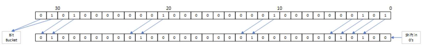
Figure 12: Left Shift Logical
LSR instructions
The Logical Shift Right (lsr) is the opposite of the lsl operation in that it shifts bits from the left to the right in a register. The bits that are moved into the register are given a value of a binary ‘0’, and the bits that are shifted out are simply lost. The formats for the LSR operation are:
  LSR Rd, Rm, #ShAmt
  LSR Rd, Rm, Rs
In these instructions, the value in Rm is shifted by the amount in either the ShAmt if a constant is given, or by the amount in the Rs register. If the size of the shift using the register is greater than 5 bits (> 31), only the 5 least significant bits are used, effectively producing a value of n%32, or the remainder from dividing the size of the shift by 32. An example of using both formats is the following.
  LSR r1, r2, #2
  LSR r1, r2, r3
The result of running the first operation is illustrated in the following diagram.
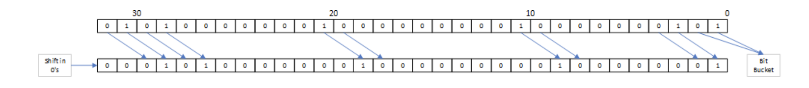 Figure 13: Right Shift Logical
ASR instructions
The Arithmetic Shift Right (ASR) is similar to the LSR operation in that it shifts bits from the left to the right in a register, and bits that are shifted out are simply lost. However, the ASR instruction does not always shift in a binary ‘0’ to the bits moved into the register. Instead, the sign bit of the integer number is shifted in these bits. This allows operations such as the division of 2 to be done by the ASR. The formats for the ASR operation are:
  ASR Rd, Rm, #ShAmt
  ASR Rd, Rm, Rs
In these instructions, the value in Rm is shifted by the amount in either the ShAmt if a constant is given, or by the amount in the Rs register. If the size of the shift using the register is greater than 5 bits (> 31), only the 5 least significant bits are used, effectively producing a value of n%32, or the remainder from dividing the size of the shift by 32. An example of using both formats is the following.
  ASR r1, r2, #2
  ASR r1, r2, r3
The result of running the first operation is illustrated in the following diagrams. In the first diagram, a positive integer number is shifted right, so the sign bit is ‘0’, and the value shifted in is a binary ‘0’.
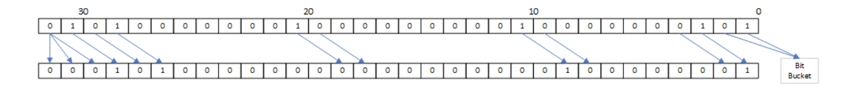
Figure 14: Arithmetic shift for positive value
In the second diagram, a negative integer number is shifted right, so the sign bit is ‘1’, and the value shifted in is a binary ‘1’.
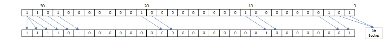
Figure 15: Arithmetic shift for negative value
ROR and RRX instructions
The Rotate Right (ROR) and Rotate Right extended (RRX) instructions allow the bits in a register to be rotated in that register. To understand this, imagine that the lowest order bit in the register is connected to the highest order bit, as in the following diagram.
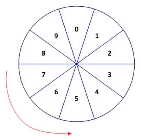
Figure 16: Rotate illustration
In this diagram the value in bit 0 is shifted into the value of bit 9, and the rest of the bits are shifted just as in the LSR. An example of this is given in the following diagram or an ROR with a 2 bit shift.
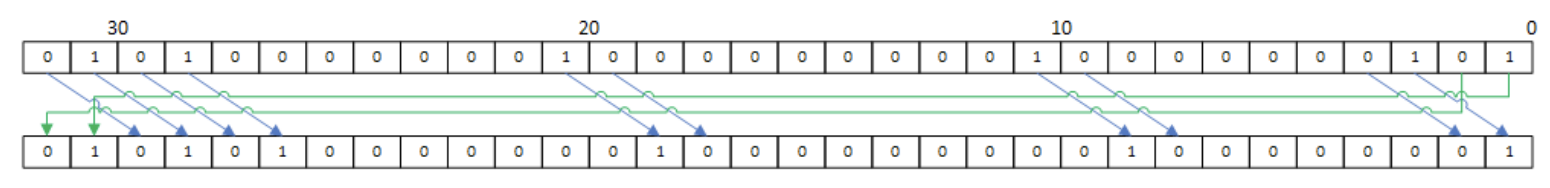
Figure 17: Rotate operation
The RRX instruction is similar to the ROR instruction, except that the carry-bit is used to store the value that is shifted out, and the current value of the carry-bit is used for the bit to set the highest order bit in the register. This is illustrated in the following diagram.
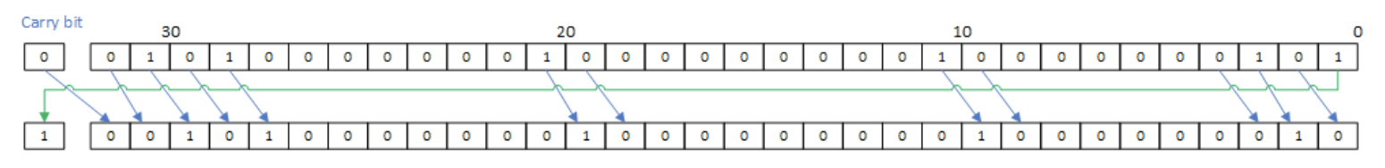
Figure 18: Rotate Extended Operation
Reasons for shift instructions
There are many reasons to do a shift operation. First, shifts make multiplication and division by powers of 2 easier to implement and faster in assembly. For example, the following examples of ARM assembly instructions multiply r1 by 2, by 8, and divides it by 4.
    LSL r0, r0, #1
    LSL r0, r0, #3
    ASR r0, r0, #2
Note that while these shifts could be used for multiplication and division in a HLL, they should almost never be used for this purpose, as any decent modern compiler will automatically implement the appropriate operations for the underlying architecture. The resulting code will always more likely be correct and the source program will be easier to understand. Having said that, however, in assembly there is no compiler to provide these operations, so it is correct to use bit shifting for multiplication and division in assembly.
There are many other reasons for using the shift operations. Some algorithms, such as some multiplication and division algorithms, rely on these operations. These operations can also be used to check bits that match hardware or software flags. Most reasons for using these operations deal with low level programming, such as device drivers, and as such many programmers will be able to have a successful career without ever using them. Some algorithms that illustrate the use of these operations will be given in the problems section of Chapter 9.