
1.3: Getting Organized - Layers
- Page ID
- 58488
\( \newcommand{\vecs}[1]{\overset { \scriptstyle \rightharpoonup} {\mathbf{#1}} } \)
\( \newcommand{\vecd}[1]{\overset{-\!-\!\rightharpoonup}{\vphantom{a}\smash {#1}}} \)
\( \newcommand{\dsum}{\displaystyle\sum\limits} \)
\( \newcommand{\dint}{\displaystyle\int\limits} \)
\( \newcommand{\dlim}{\displaystyle\lim\limits} \)
\( \newcommand{\id}{\mathrm{id}}\) \( \newcommand{\Span}{\mathrm{span}}\)
( \newcommand{\kernel}{\mathrm{null}\,}\) \( \newcommand{\range}{\mathrm{range}\,}\)
\( \newcommand{\RealPart}{\mathrm{Re}}\) \( \newcommand{\ImaginaryPart}{\mathrm{Im}}\)
\( \newcommand{\Argument}{\mathrm{Arg}}\) \( \newcommand{\norm}[1]{\| #1 \|}\)
\( \newcommand{\inner}[2]{\langle #1, #2 \rangle}\)
\( \newcommand{\Span}{\mathrm{span}}\)
\( \newcommand{\id}{\mathrm{id}}\)
\( \newcommand{\Span}{\mathrm{span}}\)
\( \newcommand{\kernel}{\mathrm{null}\,}\)
\( \newcommand{\range}{\mathrm{range}\,}\)
\( \newcommand{\RealPart}{\mathrm{Re}}\)
\( \newcommand{\ImaginaryPart}{\mathrm{Im}}\)
\( \newcommand{\Argument}{\mathrm{Arg}}\)
\( \newcommand{\norm}[1]{\| #1 \|}\)
\( \newcommand{\inner}[2]{\langle #1, #2 \rangle}\)
\( \newcommand{\Span}{\mathrm{span}}\) \( \newcommand{\AA}{\unicode[.8,0]{x212B}}\)
\( \newcommand{\vectorA}[1]{\vec{#1}} % arrow\)
\( \newcommand{\vectorAt}[1]{\vec{\text{#1}}} % arrow\)
\( \newcommand{\vectorB}[1]{\overset { \scriptstyle \rightharpoonup} {\mathbf{#1}} } \)
\( \newcommand{\vectorC}[1]{\textbf{#1}} \)
\( \newcommand{\vectorD}[1]{\overrightarrow{#1}} \)
\( \newcommand{\vectorDt}[1]{\overrightarrow{\text{#1}}} \)
\( \newcommand{\vectE}[1]{\overset{-\!-\!\rightharpoonup}{\vphantom{a}\smash{\mathbf {#1}}}} \)
\( \newcommand{\vecs}[1]{\overset { \scriptstyle \rightharpoonup} {\mathbf{#1}} } \)
\(\newcommand{\longvect}{\overrightarrow}\)
\( \newcommand{\vecd}[1]{\overset{-\!-\!\rightharpoonup}{\vphantom{a}\smash {#1}}} \)
\(\newcommand{\avec}{\mathbf a}\) \(\newcommand{\bvec}{\mathbf b}\) \(\newcommand{\cvec}{\mathbf c}\) \(\newcommand{\dvec}{\mathbf d}\) \(\newcommand{\dtil}{\widetilde{\mathbf d}}\) \(\newcommand{\evec}{\mathbf e}\) \(\newcommand{\fvec}{\mathbf f}\) \(\newcommand{\nvec}{\mathbf n}\) \(\newcommand{\pvec}{\mathbf p}\) \(\newcommand{\qvec}{\mathbf q}\) \(\newcommand{\svec}{\mathbf s}\) \(\newcommand{\tvec}{\mathbf t}\) \(\newcommand{\uvec}{\mathbf u}\) \(\newcommand{\vvec}{\mathbf v}\) \(\newcommand{\wvec}{\mathbf w}\) \(\newcommand{\xvec}{\mathbf x}\) \(\newcommand{\yvec}{\mathbf y}\) \(\newcommand{\zvec}{\mathbf z}\) \(\newcommand{\rvec}{\mathbf r}\) \(\newcommand{\mvec}{\mathbf m}\) \(\newcommand{\zerovec}{\mathbf 0}\) \(\newcommand{\onevec}{\mathbf 1}\) \(\newcommand{\real}{\mathbb R}\) \(\newcommand{\twovec}[2]{\left[\begin{array}{r}#1 \\ #2 \end{array}\right]}\) \(\newcommand{\ctwovec}[2]{\left[\begin{array}{c}#1 \\ #2 \end{array}\right]}\) \(\newcommand{\threevec}[3]{\left[\begin{array}{r}#1 \\ #2 \\ #3 \end{array}\right]}\) \(\newcommand{\cthreevec}[3]{\left[\begin{array}{c}#1 \\ #2 \\ #3 \end{array}\right]}\) \(\newcommand{\fourvec}[4]{\left[\begin{array}{r}#1 \\ #2 \\ #3 \\ #4 \end{array}\right]}\) \(\newcommand{\cfourvec}[4]{\left[\begin{array}{c}#1 \\ #2 \\ #3 \\ #4 \end{array}\right]}\) \(\newcommand{\fivevec}[5]{\left[\begin{array}{r}#1 \\ #2 \\ #3 \\ #4 \\ #5 \\ \end{array}\right]}\) \(\newcommand{\cfivevec}[5]{\left[\begin{array}{c}#1 \\ #2 \\ #3 \\ #4 \\ #5 \\ \end{array}\right]}\) \(\newcommand{\mattwo}[4]{\left[\begin{array}{rr}#1 \amp #2 \\ #3 \amp #4 \\ \end{array}\right]}\) \(\newcommand{\laspan}[1]{\text{Span}\{#1\}}\) \(\newcommand{\bcal}{\cal B}\) \(\newcommand{\ccal}{\cal C}\) \(\newcommand{\scal}{\cal S}\) \(\newcommand{\wcal}{\cal W}\) \(\newcommand{\ecal}{\cal E}\) \(\newcommand{\coords}[2]{\left\{#1\right\}_{#2}}\) \(\newcommand{\gray}[1]{\color{gray}{#1}}\) \(\newcommand{\lgray}[1]{\color{lightgray}{#1}}\) \(\newcommand{\rank}{\operatorname{rank}}\) \(\newcommand{\row}{\text{Row}}\) \(\newcommand{\col}{\text{Col}}\) \(\renewcommand{\row}{\text{Row}}\) \(\newcommand{\nul}{\text{Nul}}\) \(\newcommand{\var}{\text{Var}}\) \(\newcommand{\corr}{\text{corr}}\) \(\newcommand{\len}[1]{\left|#1\right|}\) \(\newcommand{\bbar}{\overline{\bvec}}\) \(\newcommand{\bhat}{\widehat{\bvec}}\) \(\newcommand{\bperp}{\bvec^\perp}\) \(\newcommand{\xhat}{\widehat{\xvec}}\) \(\newcommand{\vhat}{\widehat{\vvec}}\) \(\newcommand{\uhat}{\widehat{\uvec}}\) \(\newcommand{\what}{\widehat{\wvec}}\) \(\newcommand{\Sighat}{\widehat{\Sigma}}\) \(\newcommand{\lt}{<}\) \(\newcommand{\gt}{>}\) \(\newcommand{\amp}{&}\) \(\definecolor{fillinmathshade}{gray}{0.9}\)To deal with the interesting properties of networks that we identified in Section 1.2, it is necessary to get organized. The primary organizing tool for networks is an example of the design principle adopt sweeping simplifications. All networks use the divide-and-conquer technique known as layering of protocols. But before we come to layers, we must establish what a protocol is.
Suppose we are examining the set of programs used by a defense contractor who is retooling for a new business, video games. In the main program we find the procedure call
FIRE (#_of_missiles, target, action_if_defended)
and elsewhere we find the corresponding procedure, which begins
procedure FIRE (nmissiles, where, reaction)
These constructs are interpreted at two levels. First, the system matches the nameFIREin the main program with the program that exports a procedure of the same name, and it arranges to transfer control from the main program to that procedure. The procedure, in turn, matches the arguments of the calling program, position by position, with its own parameters. Thus, in this example, the second argument target of the calling program is matched with the second parameter where of the called procedure. Beyond this mechanical matching, there is an implicit agreement between the programmer of the main program and the programmer of the procedure that this second argument is to be interpreted as the location that the missiles are intended to hit.
This set of agreements on how to interpret both the order and the meaning of the arguments stands as a kind of contract between the two programs. In programming languages, such contracts are called “specifications”; in networks, such contracts are called protocols. More generally, a protocol goes beyond just the interpretation of the arguments; it encompasses everything that either of the two parties can depend on about how the other will act or react. For example, in a client/service system, a request/response protocol might specify that the service send an immediate acknowledgment when it gets a request, so that the client knows that the service is there, and send the eventual response as a third message.
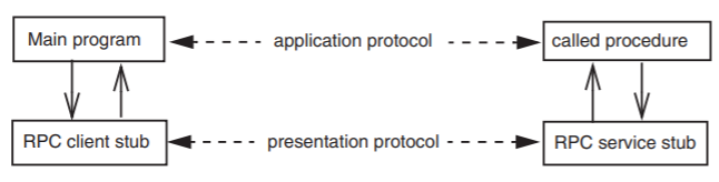
Let us suppose that our defense contractor wishes to further convert the software from a single-user game to a multiuser game, using a client/service organization. The main program will run as a client and the FIRE program will now run in a multiclient, game-coordinating service. To simplify the conversion, the contractor has chosen to use the remote procedure call (RPC) protocol illustrated in Figure \(\PageIndex{1}\). A stub procedure that runs in the client machine exports the name FIRE so that when the main program calls FIRE, control actually passes to the stub with that name. The stub collects the arguments, marshals them into a request message, and sends them over the network to the game-coordinating service. At the service, a corresponding stub waits for such a request to arrive, unmarshals the arguments in the request message, and uses them to perform a call to the real FIRE procedure. When FIRE completes its operation and returns, the service stub marshals any output value into a response message and sends it to the client. The client stub waits for this response message, and when it arrives, it unmarshals the return value in the response message and returns it as its own value to the main program. The procedure call protocol has been honored and the main program continues as if the procedure named FIRE had executed locally.
.png?revision=1)
Figure \(\PageIndex{1}\): A remote procedure call.
Figure \(\PageIndex{1}\) also illustrates a second, somewhat different, protocol between the client stub and the service stub, as compared with the protocol between the main program and the procedure it calls. Between the two stubs the request message spells out the name of the procedure to be called, the number of arguments, and the types of each argument. The details of the protocol between the RPC stubs need have little in common with the corresponding details of the protocol between the original main program and the procedure it calls.
.png?revision=1)
Figure \(\PageIndex{2}\): Two protocol layers.
Layers
In that example, the independence of the MAIN-to-FIRE procedure call protocol from the RPC stub-to-stub protocol is characteristic of a layered design. We can make those layers explicit by redrawing our picture as in Figure \(\PageIndex{2}\). The contract between the main program and the procedure it calls is called the application protocol. The contract between the client-side and service-side RPC stubs protocol is known as a presentation protocol because it translates data formats and semantics to and from locally preferred forms.
The request message must get from the client RPC stub to the service RPC stub. To communicate, the client stub calls some network procedure, using an elaboration of the SEND abstraction:
SEND_MESSAGE (request_message, service_name)
specifying in a second argument the identity of the service that should receive this request message. The service stub invokes a similar procedure that provides the RECEIVE abstraction to pick up the message. These two procedures represent a third layer, which provides a transport protocol, and we can extend our layered protocol picture as in Figure \(\PageIndex{3}\).
.png?revision=1)
Figure \(\PageIndex{3}\): Three protocol layers.
This figure makes apparent an important property of layering as used in network designs: every module has not two, but three interfaces. In the usual layered organization, a module has just two interfaces, an interface to the layer above, which hides a second interface to the layer below. But as used in a network, layering involves a third interface. Consider, for example, the RPC client stub in the figure. As expected, it provides an interface that the main program can use, and it uses an interface of the client network package below. But the whole point of the RPC client stub is to construct a request message that convinces its correspondent stub at the service to do something. The presentation protocol thus represents a third interface of the presentation layer module. The presentation module thus hides both the lower layer interface and the presentation protocol from the layer above. This observation is a general one—each layer in a network implementation provides an interface to the layer above, and it hides the interface to the layer below as well as the protocol interface to the correspondent with which it communicates.
.png?revision=1)
Figure \(\PageIndex{4}\): A layered system.
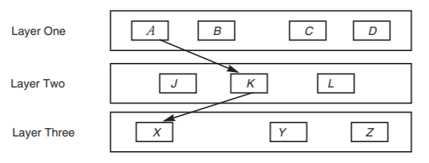
Layered design has proven to be especially effective, and it is used in some form in virtually every network implementation. The primary idea of layers is that each layer hides the operation of the layer below from the layer above, and instead provides its own interpretation of all the important features of the lower layer. Every module is assigned to some layer, and interconnections are restricted to go between modules in adjacent layers. Thus in the three-layer system of Figure \(\PageIndex{4}\), module A may call any of the modules J , K , or L , but A doesn't even know of the existence of X , Y , and Z . The figure shows A using module K . Module K , in turn, may call any of X , Y , or Z .
Different network designs, of course, will have different layering strategies. The particular layers we have discussed are only an illustration—as we investigate the design of the transport protocol of Figure \(\PageIndex{3}\) in more detail, we will find it useful to impose further layers, using a three-layer reference model that provides quite a bit of insight into how networks are organized. Our choice strongly resembles the layering that is used in the design of the Internet. The three layers we choose divide the problem of implementing a network as follows (from the bottom up):
- The link layer: moving data directly from one point to another.
- The network layer: forwarding data through intermediate points to move it to the place it is wanted.
- The end-to-end layer: everything else required to provide a comfortable application interface.
The application itself can be thought of as a fourth, highest layer, not part of the network. On the other hand, some applications intertwine themselves so thoroughly with the end-to-end layer that it is hard to make a distinction.
The terms frame, packet, segment, message, and stream that were introduced in Section 1.2 can now be identified with these layers. Each is the unit of transmission of one of the protocol layers. Working from the top down, an application starts by asking the end-to-end layer to transmit a message or a stream of data to a correspondent. The end-to-end layer splits long messages and streams into segments, it copes with lost or duplicated segments, it places arriving segments in proper order, it enforces specific communication semantics, it performs presentation transformations, and it calls on the network layer to transmit each segment. The network layer accepts segments from the end-to-end layer, constructs packets, and transmits those packets across the network, choosing which links to follow to move a given packet from its origin to its destination. The link layer accepts packets from the network layer, and constructs and transmits frames across a single link between two forwarders or between a forwarder and a customer of the network.
Some network designs attempt to impose a strict layering among various parts of what we call the end-to-end layer, but it is often such a hodgepodge of function that no single layering can describe it in a useful way. On the other hand, the network and link layers are encountered frequently enough in data communication networks that one can almost consider them universal.
With this high-level model in mind, we next sketch the basic contracts for each of the three layers and show how they relate to one another. Later, we examine in much more depth how each of the three layers is actually implemented.
The Link Layer
At the bottom of a packet-switched network there must be some underlying communication mechanism that connects one packet switch with another or a packet switch to a customer of the network. The link layer is responsible for managing this low-level communication. The goal of the link layer is to move the bits of the packet across one (usually, but not necessarily, physical) link, hiding the particular mechanics of data transmission that are involved.
.png?revision=1)
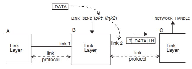
Figure \(\PageIndex{5}\): A link layer in a packet switch that has two physical links.
A typical, somewhat simplified interface to the link layer looks something like this:
LINK_SEND (data_buffer, link_identifier)
where data_buffer names a place in memory that contains a packet of information ready to be transmitted, and link_identifier names, in a local address space, one of possibly several links to use. Figure \(\PageIndex{5}\) illustrates the link layer in packet switch B, which has links to two other packet switches, A and C. The call to the link layer identifies a packet buffer named pkt and specifies that the link layer should place the packet in a frame suitable for transmission over link2, the link to packet switch C. Switches B and C both have implementations of the link layer, a program that knows the particular protocol used to send and receive frames on this link. The link layer may use a different protocol when sending a frame to switch A using link number 1. Nevertheless, the link layer typically presents a uniform interface (LINK_SEND) to higher layers. Packet switch B and packet switch C may use different labels for the link that connects them. If packet switch C has four links, the frame may arrive on what C considers to be its link number 3. The link identifier is thus a name whose scope is limited to one packet switch.
The data that actually appears on the physical wire is usually somewhat different from the data that appeared in the packet buffer at the interface to the link layer. The link layer is responsible for taking into account any special properties of the underlying physical channel, so it may, for example, encode the data in a way that is less fragile in the local noise environment, it may fragment the data because the link protocol requires shorter frames, and it may repeatedly resend the data until the other end of the link acknowledges that it has received it.
These channel-specific measures generally require that the link layer add information to the data provided by the network layer. In a layered communication system, the data passed from an upper layer to a lower layer for transmission is known as the payload. When a lower layer adds to the front of the payload some data intended only for the use of the corresponding lower layer at the other end, the addition is called a header, and when the lower layer adds something to the end, the addition is called a trailer. In Figure \(\PageIndex{5}\), the link layer has added a link layer header LH (perhaps indicating which network layer program to deliver the packet to) and a link layer trailer LT (perhaps containing a checksum for error detection). The combination of the header, payload, and trailer becomes the link-layer frame. The receiving link layer module will, after establishing that the frame has been correctly received, remove the link layer header and trailer before passing the payload to the network layer.
The particular method of waiting for a frame, packet, or message to arrive and transferring payload data and control from a lower layer to an upper layer depends on the available thread coordination procedures. Throughout this chapter, rather than having an upper layer call down to a lower-layer procedure named RECEIVE , we use upcalls, which means that when data arrives, the lower layer makes a procedure call up to an entry point in the higher layer. Thus in Figure \(\PageIndex{5}\), the link layer calls a procedure named NETWORK_HANDLE in the layer above.
The Network Layer
A segment enters a forwarding network at one of its network attachment points (the source), accompanied by instructions to deliver it to another network attachment point (the destination). To reach the destination it will probably have to traverse several links. Providing a systematic naming scheme for network attachment points, determining which links to traverse, creating a packet that contains the segment, and forwarding the packet along the intended path are the jobs of the network layer. The interface to the network layer, again somewhat simplified, resembles that of the link layer:
NETWORK_SEND (segment_buffer, network_identifier, destination)
The NETWORK_SEND procedure transmits the segment found in segment_buffer (the payload, from the point of view of the network layer), using the network named in network_identifier (a single computer may participate in more than one network), to destination (the address within that network that names the network attachment point to which the segment should be delivered).
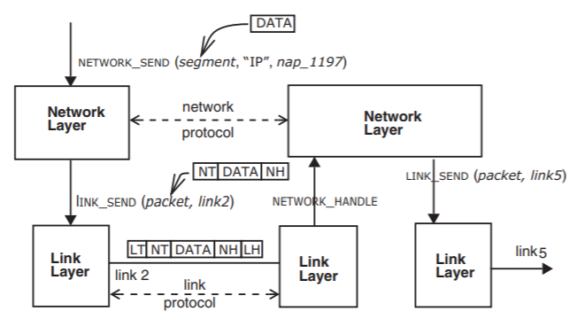
The network layer, upon receiving this call, creates a network-layer header, labeled NH in Figure \(\PageIndex{6}\), and/or trailer, labeled NT , to accompany the segment as it traverses the network named " IP ", and it assembles these components into a packet. The key item of information in the network-layer header is the address of the destination, for use by the next packet switch in the forwarding chain.
.png?revision=1)
Figure \(\PageIndex{6}\): Relation between the network layer and the link layer.
Next, the network layer consults its tables to choose the most appropriate link over which to send this packet with the goal of getting it closer to its destination. Finally, the network layer calls the link layer asking it to send the packet over the chosen link. When the frame containing the packet arrives at the other end of the link, the receiving link layer strips off the link layer header and trailer ( LH and LT in the figure) and hands the packet to its network layer by an upcall to NETWORK_HANDLE. This network layer module examines the network layer header and trailer to determine the intended destination of the packet. It consults its own tables to decide on which outgoing link to forward the packet, and it calls the link layer to send the packet on its way. The network layer of each packet switch along the way repeats this procedure, until the packet traverses the link to its destination. The network layer at the end of that link recognizes that the packet is now at its destination, it extracts the data segment from the packet, and passes that segment to the end-to-end layer, with another upcall.
The End-to-End Layer
We can now put the whole picture together. The network and link layers together provide a best-effort network, which has the "interesting" properties that were listed in Figure \(1.2.11\). These properties may be problematic to an application, and the function of the end-to-end layer is to create a less “interesting” and thus easier to use interface for the application. For example, Figure \(\PageIndex{7}\) shows the remote procedure call of Figure \(\PageIndex{1}\) from a different perspective. Here the RPC protocol is viewed as an end-to-end layer of a complete network implementation. As with the lower layers, the end-to-end layer has added a header and a trailer to the data that the application gave it, and inspecting the bits on the wire we now see three distinct headers and trailers, corresponding to the three layers of the network implementation.
The RPC implementation in the end-to-end layer provides several distinct end-toend services, each intended to hide some aspect of the underlying network from its application:
- Presentation services. Translating data formats and emulating the semantics of a procedure call. For this purpose the end-to-end header might contain, for example, a count of the number of arguments in the procedure call.
- Transport services. Dividing streams and messages into segments and dealing with lost, duplicated, and out-of-order segments. For this purpose, the end-to-end header might contain serial numbers of the segments.
- Session services. Negotiating a search, handshake, and binding sequence to locate and prepare to use a service that knows how to perform the requested procedure. For this purpose, the end-to-end header might contain a unique identifier that tells the service which client application is making this call.
Depending on the requirements of the application, different end-to-end layer implementations may provide all, some, or none of these services, and the end-to-end header and trailer may contain various different bits of information.
There is one other important property of this layering that becomes evident in examining Figure \(\PageIndex{7}\). Each layer considers the payload transmitted by the layer above to be information that it is not expected, or even permitted, to interpret. Thus the end-to-end layer constructs a segment with an end-to-end header and trailer that it hands to the network layer, with the expectation that the network layer will not look inside or perform any actions that require interpretation of the segment. The network layer, in turn, adds a network-layer header and trailer and hands the resulting packet to the link layer, again with the expectation that the link layer will consider this packet to be an opaque string of bits, a payload to be carried in a link-layer frame. Violation of this rule would lead to interdependence across layers and consequent loss of modularity of the system.
.png?revision=1)
Figure \(\PageIndex{7}\): Three network layers in action.The arguments of the procedure call become the payload of the end-to-end segment. The network layer forwards the packet across two links on the way from the client to the service.The frame on the wire contains the headers and trailers of three layers.
Additional Layers and the End-to-End Argument
To this point, we have suggested that a three-layer reference model is both necessary and sufficient to provide insight into how networks operate. Standard textbooks on network design and implementation mention a reference model from the International Organization for Standardization, known as "Open Systems Interconnect", or OSI. The OSI reference model has not three, but seven layers. What is the difference?
There are several differences. Some are trivial; for example, the OSI reference model divides the link layer into a strategy layer (known as the "data link layer") and a physical layer, recognizing that many different kinds of physical links can be managed with a small number of management strategies. There is a much more significant difference between our reference model and the OSI reference model in the upper layers. The OSI reference model systematically divides our end-to-end layer into four distinct layers. Three of these layers directly correspond, in the RPC example, to the layers of Figure \(\PageIndex{3}\): an application layer, a presentation layer, and a transport layer. In addition, just above the transport layer, the ISO model inserts a layer that provides the session services mentioned just above.
We have avoided this approach for the simple reason that different applications have radically different requirements for transport, session, and presentation services—even to the extent that the order in which they should be applied may be different. This situation makes it difficult to propose any single layering, since a layering implies an ordering.
For example, an application that consists of sending a file to a printer would find most useful a transport service that guarantees to deliver to the printer a stream of bytes in the same order in which they were sent, with none missing and none duplicated. But a file transfer application might not care in what order different blocks of the file are delivered, so long as they all eventually arrive at the destination. A digital telephone application would like to see a stream of bits representing successive samples of the sound waveform delivered in proper order, but here and there a few samples can be missing without interfering with the intelligibility of the conversation. This rather wide range of application requirements suggests that any implementation decisions that a lower layer makes (for example, to wait for out-of-order segments to arrive so that data can be delivered in the correct order to the next higher layer) may be counterproductive for at least some applications. Instead, it is likely to be more effective to provide a library of service modules that can be selected and organized by the programmer of a specific application. Thus, our end-to-end layer is an unstructured library of service modules, of which the RPC protocol is an example.
This argument against additional layers is an example of a design principle known as
The End-to-End Argument
The application knows best.
In this case, the basic thrust of the end-to-end argument is that the application knows best what its real communication requirements are, and for a lower network layer to try to implement any feature other than transporting the data risks implementing something that isn't quite what the application needed. Moreover, if it isn't exactly what is needed, the application will probably have to re-implement that function on its own. The end-to-end argument can thus be paraphrased as: don't bury it in a lower layer, let the end points deal with it because they know best what they need.
A simple example of this phenomenon is file transfer. To transfer a file carefully, the appropriate method is to calculate a checksum from the contents of the file as it is stored in the file system of the originating site. Then, after the file has been transferred and written to the new file system, the receiving site should read the file back out of its file system, recalculate the checksum anew, and compare it with the original checksum. If the two checksums are the same, the file transfer application has quite a bit of confidence that the new site has a correct copy; if they are different, something went wrong and recovery is needed.
Given this end-to-end approach to checking the accuracy of the file transfer, one can question whether or not there is any value in, for example, having the link layer protocol add a frame checksum to the link layer trailer. This link layer checksum takes time to calculate, it adds to the data to be sent, and it verifies the correctness of the data only while it is being transmitted across that link. Despite this protection, the data may still be damaged while it is being passed through the network layer, or while it is buffered by the receiving part of the file transfer application, or while it is being written to the disk. Because of those threats, the careful file transfer application cannot avoid calculating its end-to-end checksum, despite the protection provided by the link layer checksum.
This is not to say that the link layer checksum is worthless. If the link layer provides a checksum, that layer will discover data transmission errors at a time when they can be easily corrected by resending just one frame. Absent this link-layer checksum, a transmission error will not be discovered until the end-to-end layer verifies its checksum, by which point it may be necessary to redo the entire file transfer. So there may be a significant performance gain in having this feature in a lower-level layer. The interesting observation is that a lower-layer checksum does not eliminate the need for the application layer to implement the function, and it is thus not required for application correctness. It is just a performance enhancement.
The end-to-end argument can be applied to a variety of system design issues in addition to network design. It does not provide an absolute decision technique, but rather a useful argument that should be weighed against other arguments in deciding where to place function.
Mapped and Recursive Applications of the Layered Model
When one begins decomposing a particular existing network into link, network, and end-to-end layers, it sometimes becomes apparent that some of the layers of the network are themselves composed of what are obviously link, network, or end-to-end layers. These compositions come in two forms: mapped and recursive.
Mapped composition occurs when a network layer is built directly on another network layer by mapping higher-layer network addresses to lower-layer network addresses. A typical application for mapping arises when a better or more popular network technology comes along, yet it is desirable to keep running applications that are designed for the old network. For example, Apple designed a network called Appletalk that was used for many years, and then later mapped the Appletalk network layer to the Ethernet, which, as described in Section 1.9, has a network and link layer of its own but uses a somewhat different scheme for its network layer addresses.
Another application for mapped composition is to interconnect several independently designed network layers, a scheme called internetworking. Probably the best example of internetworking is the Internet itself (described in Sidebar \(\PageIndex{1}\)), which links together many different network layers by mapping them all to a universal network layer that uses a protocol known as Internet protocol (IP). Section 1.9 explains how the network layer addresses of the Ethernet are mapped to and from the IP addresses of the Internet using what is known as an Address Resolution Protocol. The Internet also maps the internal network addresses of many other networks—wireless networks, satellite networks, cable TV networks, etc.—into IP addresses.
Sidebar \(\PageIndex{1}\)
- The Internet
-
The Internet provides examples of nearly every concept in this chapter. Much of the Internet is a network layer that is mapped onto some other network layer such as a satellite network, a wireless network, or an Ethernet. Internet protocol (IP) is the primary network layer protocol, but it is not the only network layer protocol used in the Internet. There is a network layer protocol for managing the Internet, known as ICMP. There are also several different network layer routing protocols, some providing routing within small parts of the Internet, others providing routing between major regions. But every point that can be reached via the Internet implements IP.
The link layer of the Internet includes all of the link layers of the networks that the Internet maps onto and it also includes many separate, specialized links: a wire, a dial-up telephone line, a dedicated line provided by the telephone company, a microwave link, a digital subscriber line (DSL), a free-space optical link, etc. Almost anything that carries bits has been used somewhere as a link in the Internet.
The end-to-end protocols used on the Internet are many and varied. The primary transport protocols are TCP, UDP, and RTP, described briefly in Section 1.6.1. Built on these transport protocols are hundreds of application protocols. A short list of some of the most widely used application protocols would include file transfer (FTP), the World Wide Web (HTTP), mail dispatch and pickup (SMTP and POP), text messaging (IRC), telephone (VoIP), and file exchange (Gnutella, bittorrent, etc.).
The current chapter presents a general model of networks, rather than a description of the Internet. To learn more about the Internet, see the books and papers listed in the section for Chapter 1 in the Suggestions for Further Reading.
Recursive composition occurs when a network layer rests on a link layer that itself is a complete three-layer network. Recursive composition is not a general property of layers, but rather it is a specific property of layered communication systems: The send/receive semantics of an end-to-end connection through a network can be designed to be have the same semantics as a single link, so such an end-to-end connection can be used as a link in a higher-level network. That property facilitates recursive composition, as well as the implementation of various interesting and useful network structures. Here are some examples of recursive composition:
- A dial-up telephone line is often used as a link to an attachment point of the Internet. This dial-up line goes through a telephone network that has its own link, network, and end-to-end layers.
- An overlay network is a network layer structure that uses as links the end-to-end layer of an existing network. Gnutella (see problem set 20) is an example of an overlay network that uses the end-to-end layer of the Internet for its links.
- With the advance of "voice over IP" (VoIP), the traditional voice telephone network is gradually converting to become an overlay on the Internet.
- A tunnel is a structure that uses the end-to-end layer of an existing network as a link between a local network-layer attachment point and a distant one to make it appear that the attachment is at the distant point. Tunnels, combined with the encryption techniques described in Chapter 5, are used to implement what is commonly called a "virtual private network" (VPN).
Recursive composition need not be limited to two levels. Figure \(\PageIndex{8}\) illustrates the case of Gnutella overlaying the Internet, with a dial-up telephone connection being used as the Internet link layer.
The primary concern when one is dealing with a link layer that is actually an end-to-end connection through another network is that discussion can become confusing unless one is careful to identify which level of decomposition is under discussion. Fortunately our terminology helps keep track of the distinctions among the various layers of a network, so it is worth briefly reviewing that terminology. At the interface between the application and the end-to-end layer, data is identified as a stream or message. The end-to-end layer divides the stream or message up into a series of segments and hands them to the network layer for delivery. The network layer encapsulates each segment in a packet which it forwards through the network with the help of the link layer. The link layer transmits the packet in a frame. If the link layer is itself a network, then this frame is a message as viewed by the underlying network.
This discussion of layered network organization has been both general and abstract. In the next three sections we investigate in more depth the usual functions and some typical implementation techniques of each of the three layers of our reference model. However, as the introduction pointed out, what follows is not a comprehensive treatment of networking. Instead it identifies many of the major issues and for each issue exhibits one or two examples of how that issue is typically handled in a real network design. For readers who have a goal of becoming network engineers, and who therefore would like to learn the whole remarkable range of implementation strategies that have been used in networks, the Suggestions for Further Reading list several comprehensive books on the subject.
.png?revision=1)
Figure \(\PageIndex{8}\): A typical recursive network composition.The overlay network Gnutella uses for its link layer an end-to-end transport protocol of the Internet. The Internet uses for one of its links an end-to-end transport protocol of the dial-up telephone system.