
2.4: Amplifier Efficiency
- Page ID
- 46026
There are several ways of expressing amplifier efficiency depending on how the RF input power is treated. One measure of efficiency of a circuit is the useful output power divided by the input power, and considers the contribution of the RF input power. This measure of efficiency is called power-added efficiency (PAE). At RF and microwave frequencies, the most common definition of PAE used with power amplifiers focuses on the additional RF power divided by the DC input power. Thus
\[\label{eq:1}\eta_{\text{PAE}}=\frac{P_{\text{RF, out}}-P_{\text{RF, in}}}{P_{\text{DC}}} \]
There is another definition of PAE, but it is less commonly used at RF and microwave frequencies [8]. However, this alternative definition can be used with any two-port network. RF and microwave circuit designers refer to this as the total power-added efficiency and at lower frequencies it is called the transmit chain efficiency. This efficiency is denoted \(\eta_{\text{total}}\) and is defined as
\[\label{eq:2}\eta_{\text{total}}=\frac{P_{\text{RF, out}}}{P_{\text{DC}}+P_{\text{RF, in}}} \]
RF engineers also refer to this as the overall amplifier efficiency:
\[\label{eq:3}\eta_{\text{overall}}=\eta_{\text{total}}=\frac{P_{\text{RF, out}}}{P_{\text{DC}}+P_{\text{RF, in}}} \]
A final definition is the average amplifier efficiency, \(\eta_{\text{avg}}\) [9]. This metric takes into account the time-varying level of a modulated communications
| Power gain \((\text{dB})\) | \(\eta_{\text{TOTAL}}\) | \(\eta_{\text{PAE}}\) | \(\eta_{D}\) |
|---|---|---|---|
| \(3\) | \(40\%\) | \(25\%\) | \(50\%\) |
| \(6\) | \(44\%\) | \(37\%\) | \(50\%\) |
| \(10\) | \(48\%\) | \(45\%\) | \(50\%\) |
| \(15\) | \(49\%\) | \(48\%\) | \(50\%\) |
| \(20\) | \(50\%\) | \(50\%\) | \(50\%\) |
| \(40\) | \(50\%\) | \(50\%\) | \(50\%\) |
Table \(\PageIndex{1}\): Comparison of efficiency metrics for an amplifier producing \(1\text{ W}\) RF output power and consuming \(2\text{ W}\) of DC power with various power gains.
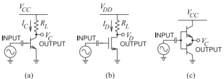
Figure \(\PageIndex{1}\): Class A singleended resistively biased amplifiers: (a) BJT transistor with B for base terminal, C for collector terminal, and E for emitter terminal; (b) MOSFET transistor with G for gate terminal, D for drain terminal, and S for source terminal; and (c) Class B or Class C push-pull amplifier.
signal and is the ratio of the average RF output power to the average DC input power:
\[\label{eq:4}\eta_{\text{avg}}=\frac{P_{\text{RF, out, avg}}}{P_{\text{DC, avg}}} \]
For high-gain amplifiers, \(P_{\text{RF, in}} ≪ P_{\text{DC}}\), and all of the efficiencies become approximately equivalent and is simply called the efficiency, \(\eta\), of the amplifier:
\[\label{eq:5}\eta=\frac{P_{\text{RF, out}}}{P_{\text{DC}}}\approx\eta_{\text{PAE}}\approx\eta_{\text{total}}\approx\eta_{\text{avg}}\approx\eta_{\text{overall}}\quad\text{(high gain)} \]
When the primary input DC power is fed to the drain of a FET, the term drain efficiency, \(\eta_{D}\), is used:
\[\label{eq:6}\eta_{D}=\frac{P_{\text{RF, out}}}{P_{\text{DC}}} \]
This term is also used when the device is a BJT or HBT, although the term collector efficiency would be more appropriate.
The efficiency metrics are compared in Table \(\PageIndex{1}\) for an amplifier with \(1\text{ W}\) RF output power. The first amplifier has a power gain of \(3\text{ dB}\), which is commonly the gain of the final amplifier stage producing the maximum output power available from a particular transistor technology.