
2.2: SYMBOLOGY
- Page ID
- 58438

Elements common to many electronic feedback systems are shown in Figure 2.1. The input signal is applied directly to a comparator. The output signal is determined and possibly operated upon by a feedback element. The difference between the input signal and the modified output signal is determined by the comparator and is a measure of the error or amount by which the output differs from its desired value. An amplifier drives the out put in such a way as to reduce the magnitude of the error signal. The system output may also be influenced by disturbances that affect the amplifier or other elements.
We shall find it convenient to illustrate the relationships among variables in a feedback connection, such as that shown in Figure 2.1, by means of block diagrams.A block diagram includes three types of elements.
- A line represents a variable, with an arrow on the line indicating the direction of information flow. A line may split, indicating that a single variable is supplied to two or more portions of the system.
- A block operates on an input supplied to it to provide an output.
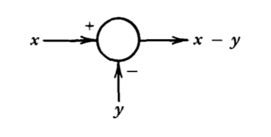
- Variables are added algebraically at a summation point drawn as follows:
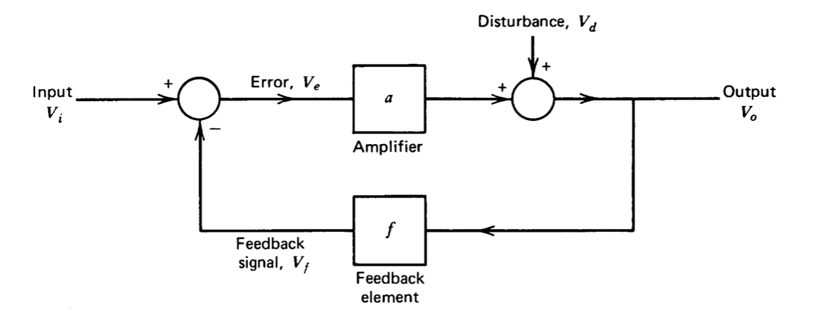
One possible representation for the system of Figure 2.1, assuming that the input, output, and disturbance are voltages, is shown in block-diagram form in Figure 2.2. (The voltages are all assumed to be measured with respect to references or grounds that are not shown.) The block diagram implies a specific set of relationships among system variables, including:
- The error is the difference between the input signal and the feedback signal, or \(V_e = V_i - V_f\).
- The output is the sum of the disturbance and the amplified error signal, or \(V_o = V_d + aV_e\).
- The feedback signal is obtained by operating on the output signal with the feedback element, or \(V_f=fV_o\).
The three relationships can be combined and solved for the output in terms of the input and the disturbance, yielding
\[V_o = \dfrac{aV_i}{1+af} + \dfrac{V_d}{1 + af} \nonumber \]