24.1: Introduction
- Page ID
- 32715
\( \newcommand{\vecs}[1]{\overset { \scriptstyle \rightharpoonup} {\mathbf{#1}} } \)
\( \newcommand{\vecd}[1]{\overset{-\!-\!\rightharpoonup}{\vphantom{a}\smash {#1}}} \)
\( \newcommand{\dsum}{\displaystyle\sum\limits} \)
\( \newcommand{\dint}{\displaystyle\int\limits} \)
\( \newcommand{\dlim}{\displaystyle\lim\limits} \)
\( \newcommand{\id}{\mathrm{id}}\) \( \newcommand{\Span}{\mathrm{span}}\)
( \newcommand{\kernel}{\mathrm{null}\,}\) \( \newcommand{\range}{\mathrm{range}\,}\)
\( \newcommand{\RealPart}{\mathrm{Re}}\) \( \newcommand{\ImaginaryPart}{\mathrm{Im}}\)
\( \newcommand{\Argument}{\mathrm{Arg}}\) \( \newcommand{\norm}[1]{\| #1 \|}\)
\( \newcommand{\inner}[2]{\langle #1, #2 \rangle}\)
\( \newcommand{\Span}{\mathrm{span}}\)
\( \newcommand{\id}{\mathrm{id}}\)
\( \newcommand{\Span}{\mathrm{span}}\)
\( \newcommand{\kernel}{\mathrm{null}\,}\)
\( \newcommand{\range}{\mathrm{range}\,}\)
\( \newcommand{\RealPart}{\mathrm{Re}}\)
\( \newcommand{\ImaginaryPart}{\mathrm{Im}}\)
\( \newcommand{\Argument}{\mathrm{Arg}}\)
\( \newcommand{\norm}[1]{\| #1 \|}\)
\( \newcommand{\inner}[2]{\langle #1, #2 \rangle}\)
\( \newcommand{\Span}{\mathrm{span}}\) \( \newcommand{\AA}{\unicode[.8,0]{x212B}}\)
\( \newcommand{\vectorA}[1]{\vec{#1}} % arrow\)
\( \newcommand{\vectorAt}[1]{\vec{\text{#1}}} % arrow\)
\( \newcommand{\vectorB}[1]{\overset { \scriptstyle \rightharpoonup} {\mathbf{#1}} } \)
\( \newcommand{\vectorC}[1]{\textbf{#1}} \)
\( \newcommand{\vectorD}[1]{\overrightarrow{#1}} \)
\( \newcommand{\vectorDt}[1]{\overrightarrow{\text{#1}}} \)
\( \newcommand{\vectE}[1]{\overset{-\!-\!\rightharpoonup}{\vphantom{a}\smash{\mathbf {#1}}}} \)
\( \newcommand{\vecs}[1]{\overset { \scriptstyle \rightharpoonup} {\mathbf{#1}} } \)
\(\newcommand{\longvect}{\overrightarrow}\)
\( \newcommand{\vecd}[1]{\overset{-\!-\!\rightharpoonup}{\vphantom{a}\smash {#1}}} \)
\(\newcommand{\avec}{\mathbf a}\) \(\newcommand{\bvec}{\mathbf b}\) \(\newcommand{\cvec}{\mathbf c}\) \(\newcommand{\dvec}{\mathbf d}\) \(\newcommand{\dtil}{\widetilde{\mathbf d}}\) \(\newcommand{\evec}{\mathbf e}\) \(\newcommand{\fvec}{\mathbf f}\) \(\newcommand{\nvec}{\mathbf n}\) \(\newcommand{\pvec}{\mathbf p}\) \(\newcommand{\qvec}{\mathbf q}\) \(\newcommand{\svec}{\mathbf s}\) \(\newcommand{\tvec}{\mathbf t}\) \(\newcommand{\uvec}{\mathbf u}\) \(\newcommand{\vvec}{\mathbf v}\) \(\newcommand{\wvec}{\mathbf w}\) \(\newcommand{\xvec}{\mathbf x}\) \(\newcommand{\yvec}{\mathbf y}\) \(\newcommand{\zvec}{\mathbf z}\) \(\newcommand{\rvec}{\mathbf r}\) \(\newcommand{\mvec}{\mathbf m}\) \(\newcommand{\zerovec}{\mathbf 0}\) \(\newcommand{\onevec}{\mathbf 1}\) \(\newcommand{\real}{\mathbb R}\) \(\newcommand{\twovec}[2]{\left[\begin{array}{r}#1 \\ #2 \end{array}\right]}\) \(\newcommand{\ctwovec}[2]{\left[\begin{array}{c}#1 \\ #2 \end{array}\right]}\) \(\newcommand{\threevec}[3]{\left[\begin{array}{r}#1 \\ #2 \\ #3 \end{array}\right]}\) \(\newcommand{\cthreevec}[3]{\left[\begin{array}{c}#1 \\ #2 \\ #3 \end{array}\right]}\) \(\newcommand{\fourvec}[4]{\left[\begin{array}{r}#1 \\ #2 \\ #3 \\ #4 \end{array}\right]}\) \(\newcommand{\cfourvec}[4]{\left[\begin{array}{c}#1 \\ #2 \\ #3 \\ #4 \end{array}\right]}\) \(\newcommand{\fivevec}[5]{\left[\begin{array}{r}#1 \\ #2 \\ #3 \\ #4 \\ #5 \\ \end{array}\right]}\) \(\newcommand{\cfivevec}[5]{\left[\begin{array}{c}#1 \\ #2 \\ #3 \\ #4 \\ #5 \\ \end{array}\right]}\) \(\newcommand{\mattwo}[4]{\left[\begin{array}{rr}#1 \amp #2 \\ #3 \amp #4 \\ \end{array}\right]}\) \(\newcommand{\laspan}[1]{\text{Span}\{#1\}}\) \(\newcommand{\bcal}{\cal B}\) \(\newcommand{\ccal}{\cal C}\) \(\newcommand{\scal}{\cal S}\) \(\newcommand{\wcal}{\cal W}\) \(\newcommand{\ecal}{\cal E}\) \(\newcommand{\coords}[2]{\left\{#1\right\}_{#2}}\) \(\newcommand{\gray}[1]{\color{gray}{#1}}\) \(\newcommand{\lgray}[1]{\color{lightgray}{#1}}\) \(\newcommand{\rank}{\operatorname{rank}}\) \(\newcommand{\row}{\text{Row}}\) \(\newcommand{\col}{\text{Col}}\) \(\renewcommand{\row}{\text{Row}}\) \(\newcommand{\nul}{\text{Nul}}\) \(\newcommand{\var}{\text{Var}}\) \(\newcommand{\corr}{\text{corr}}\) \(\newcommand{\len}[1]{\left|#1\right|}\) \(\newcommand{\bbar}{\overline{\bvec}}\) \(\newcommand{\bhat}{\widehat{\bvec}}\) \(\newcommand{\bperp}{\bvec^\perp}\) \(\newcommand{\xhat}{\widehat{\xvec}}\) \(\newcommand{\vhat}{\widehat{\vvec}}\) \(\newcommand{\uhat}{\widehat{\uvec}}\) \(\newcommand{\what}{\widehat{\wvec}}\) \(\newcommand{\Sighat}{\widehat{\Sigma}}\) \(\newcommand{\lt}{<}\) \(\newcommand{\gt}{>}\) \(\newcommand{\amp}{&}\) \(\definecolor{fillinmathshade}{gray}{0.9}\)The use of microelectronic devices within our daily lives has increased vastly resulting in the transformation of our lives by recent scientific and technological advances. Electromigration is a principal wear-out mechanism of integrated circuits (IC), thus limiting their reliability. Reliability is important for the success in the microelectronics industry as a product is expected to work for an extended period of time without failure. This makes electromigration an area of intense research as more and more is demanded from microprocessors – to be faster, with smaller components and cheaper.
History
An IC contains various interconnected semiconductor components, such as transistors, resistors, capacitors and diodes. The first integrated chip contained tens of transistors within a chip area of 1 cm2, and can now be called “Small-Scale Integration” (SSI). To find out more about the different parts of an integrated circuit, click here.
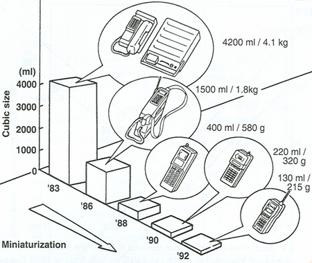
With time, there has been a reduction of the dimensions of personal computing systems, from the size of a desktop, to a notebook, to a palmtop, to a credit card, to a watch, eventually to the size of a finger ring!
Concurrently, there has been a change in volume and complexity of wireless communication system.

Reprinted from ‘Reliability and Failure of Electronic Materials and Devices’ by Milton Ohring, Copyright 1998, with permission from Elsevier.
Currently, a chip area of 1 cm2 or smaller contains hundreds of thousands of transistors to several million – “Very Large-Scale Integration” (VLSI) – making it possible to fabricate a Central Processing Unit (CPU) on a single integrated circuit. The industry now uses the terminology of “Ultra-Large-Scale Integration” (ULSI), for chips containing more than a million transistors and to emphasize chip complexity.
This continuous stream of achieving higher levels of integration brings about an exponential growth in the power of computing and communications technology to consumers and businesses worldwide. This is described by Moore’s Law.
Moore’s Law states that:
The number of transistors on an integrated circuit doubles about every two years.
Today, adding transistors in pace with Moore’s Law continues to drive increased functionality, performance and decreased cost of computing and communications technology. The price of an individual transistor has decreased drastically from $45 (in the 1950s) to less than a hundred-thousandth of a cent (currently - 2005)!
Click this link to view a graph depicting the rapid growth in the number of transistors integrated onto a single chip.
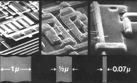
The dramatic miniaturization has involved not only the semiconductor components of an IC but also the conducting lines linking them (the interconnects – part of the metallization on a device). Changes relevant for electromigration-induced failure of interconnects include:
- line widths shrinking from 10 mm to 0.19 μm, which will become even finer in the future.
- total length of interconnect lines on a single IC increasing from several cm to several km (reaching lengths of about 5 km).
- current densities increasing from 108 A m–2 to 1010 A m–2.
- number of metal levels increasing from 1 to 7 – this is because the number of components has increased so vastly that a single level on the top of the silicon substrate is insufficient to interconnect all the semiconductor components in the substrate, thus requiring multiple levels of metallization lines.

Line widths decreasing from 1 μm to 0.5 μm (for research purposes line widths as small as 0.07 μm have been used).
Reprinted from ‘Reliability and Failure of Electronic Materials and Devices’ by Milton Ohring, Copyright 1998, with permission from Elsevier.
These changes all increase the likelihood of electromigration-induced failure of the metallization and they drive further research to reduce the effect of electromigration. The latest development is the move away from aluminium-based to copper-based metallization lines.


