31.7: Electrode Materials
- Page ID
- 32969
\( \newcommand{\vecs}[1]{\overset { \scriptstyle \rightharpoonup} {\mathbf{#1}} } \)
\( \newcommand{\vecd}[1]{\overset{-\!-\!\rightharpoonup}{\vphantom{a}\smash {#1}}} \)
\( \newcommand{\dsum}{\displaystyle\sum\limits} \)
\( \newcommand{\dint}{\displaystyle\int\limits} \)
\( \newcommand{\dlim}{\displaystyle\lim\limits} \)
\( \newcommand{\id}{\mathrm{id}}\) \( \newcommand{\Span}{\mathrm{span}}\)
( \newcommand{\kernel}{\mathrm{null}\,}\) \( \newcommand{\range}{\mathrm{range}\,}\)
\( \newcommand{\RealPart}{\mathrm{Re}}\) \( \newcommand{\ImaginaryPart}{\mathrm{Im}}\)
\( \newcommand{\Argument}{\mathrm{Arg}}\) \( \newcommand{\norm}[1]{\| #1 \|}\)
\( \newcommand{\inner}[2]{\langle #1, #2 \rangle}\)
\( \newcommand{\Span}{\mathrm{span}}\)
\( \newcommand{\id}{\mathrm{id}}\)
\( \newcommand{\Span}{\mathrm{span}}\)
\( \newcommand{\kernel}{\mathrm{null}\,}\)
\( \newcommand{\range}{\mathrm{range}\,}\)
\( \newcommand{\RealPart}{\mathrm{Re}}\)
\( \newcommand{\ImaginaryPart}{\mathrm{Im}}\)
\( \newcommand{\Argument}{\mathrm{Arg}}\)
\( \newcommand{\norm}[1]{\| #1 \|}\)
\( \newcommand{\inner}[2]{\langle #1, #2 \rangle}\)
\( \newcommand{\Span}{\mathrm{span}}\) \( \newcommand{\AA}{\unicode[.8,0]{x212B}}\)
\( \newcommand{\vectorA}[1]{\vec{#1}} % arrow\)
\( \newcommand{\vectorAt}[1]{\vec{\text{#1}}} % arrow\)
\( \newcommand{\vectorB}[1]{\overset { \scriptstyle \rightharpoonup} {\mathbf{#1}} } \)
\( \newcommand{\vectorC}[1]{\textbf{#1}} \)
\( \newcommand{\vectorD}[1]{\overrightarrow{#1}} \)
\( \newcommand{\vectorDt}[1]{\overrightarrow{\text{#1}}} \)
\( \newcommand{\vectE}[1]{\overset{-\!-\!\rightharpoonup}{\vphantom{a}\smash{\mathbf {#1}}}} \)
\( \newcommand{\vecs}[1]{\overset { \scriptstyle \rightharpoonup} {\mathbf{#1}} } \)
\(\newcommand{\longvect}{\overrightarrow}\)
\( \newcommand{\vecd}[1]{\overset{-\!-\!\rightharpoonup}{\vphantom{a}\smash {#1}}} \)
\(\newcommand{\avec}{\mathbf a}\) \(\newcommand{\bvec}{\mathbf b}\) \(\newcommand{\cvec}{\mathbf c}\) \(\newcommand{\dvec}{\mathbf d}\) \(\newcommand{\dtil}{\widetilde{\mathbf d}}\) \(\newcommand{\evec}{\mathbf e}\) \(\newcommand{\fvec}{\mathbf f}\) \(\newcommand{\nvec}{\mathbf n}\) \(\newcommand{\pvec}{\mathbf p}\) \(\newcommand{\qvec}{\mathbf q}\) \(\newcommand{\svec}{\mathbf s}\) \(\newcommand{\tvec}{\mathbf t}\) \(\newcommand{\uvec}{\mathbf u}\) \(\newcommand{\vvec}{\mathbf v}\) \(\newcommand{\wvec}{\mathbf w}\) \(\newcommand{\xvec}{\mathbf x}\) \(\newcommand{\yvec}{\mathbf y}\) \(\newcommand{\zvec}{\mathbf z}\) \(\newcommand{\rvec}{\mathbf r}\) \(\newcommand{\mvec}{\mathbf m}\) \(\newcommand{\zerovec}{\mathbf 0}\) \(\newcommand{\onevec}{\mathbf 1}\) \(\newcommand{\real}{\mathbb R}\) \(\newcommand{\twovec}[2]{\left[\begin{array}{r}#1 \\ #2 \end{array}\right]}\) \(\newcommand{\ctwovec}[2]{\left[\begin{array}{c}#1 \\ #2 \end{array}\right]}\) \(\newcommand{\threevec}[3]{\left[\begin{array}{r}#1 \\ #2 \\ #3 \end{array}\right]}\) \(\newcommand{\cthreevec}[3]{\left[\begin{array}{c}#1 \\ #2 \\ #3 \end{array}\right]}\) \(\newcommand{\fourvec}[4]{\left[\begin{array}{r}#1 \\ #2 \\ #3 \\ #4 \end{array}\right]}\) \(\newcommand{\cfourvec}[4]{\left[\begin{array}{c}#1 \\ #2 \\ #3 \\ #4 \end{array}\right]}\) \(\newcommand{\fivevec}[5]{\left[\begin{array}{r}#1 \\ #2 \\ #3 \\ #4 \\ #5 \\ \end{array}\right]}\) \(\newcommand{\cfivevec}[5]{\left[\begin{array}{c}#1 \\ #2 \\ #3 \\ #4 \\ #5 \\ \end{array}\right]}\) \(\newcommand{\mattwo}[4]{\left[\begin{array}{rr}#1 \amp #2 \\ #3 \amp #4 \\ \end{array}\right]}\) \(\newcommand{\laspan}[1]{\text{Span}\{#1\}}\) \(\newcommand{\bcal}{\cal B}\) \(\newcommand{\ccal}{\cal C}\) \(\newcommand{\scal}{\cal S}\) \(\newcommand{\wcal}{\cal W}\) \(\newcommand{\ecal}{\cal E}\) \(\newcommand{\coords}[2]{\left\{#1\right\}_{#2}}\) \(\newcommand{\gray}[1]{\color{gray}{#1}}\) \(\newcommand{\lgray}[1]{\color{lightgray}{#1}}\) \(\newcommand{\rank}{\operatorname{rank}}\) \(\newcommand{\row}{\text{Row}}\) \(\newcommand{\col}{\text{Col}}\) \(\renewcommand{\row}{\text{Row}}\) \(\newcommand{\nul}{\text{Nul}}\) \(\newcommand{\var}{\text{Var}}\) \(\newcommand{\corr}{\text{corr}}\) \(\newcommand{\len}[1]{\left|#1\right|}\) \(\newcommand{\bbar}{\overline{\bvec}}\) \(\newcommand{\bhat}{\widehat{\bvec}}\) \(\newcommand{\bperp}{\bvec^\perp}\) \(\newcommand{\xhat}{\widehat{\xvec}}\) \(\newcommand{\vhat}{\widehat{\vvec}}\) \(\newcommand{\uhat}{\widehat{\uvec}}\) \(\newcommand{\what}{\widehat{\wvec}}\) \(\newcommand{\Sighat}{\widehat{\Sigma}}\) \(\newcommand{\lt}{<}\) \(\newcommand{\gt}{>}\) \(\newcommand{\amp}{&}\) \(\definecolor{fillinmathshade}{gray}{0.9}\)This section of the TLP introduces some of the most common materials used as electrodes in SOFCs.
The electrodes have to possess the following properties to ensure a smooth operation of the fuel cell:
- High electrical conductivity
- High catalytic activity
- High surface area
- Compatibility with the electrolyte (and interconnect)
For many years, platinum was the most common and only material that was used as the electrode. The biggest disadvantage of platinum is its cost: it is economically not viable to build fuel cells with platinum electrodes. Hence the pressure to find cheaper electrode materials such as perovskites (e.g. LaCoO3 and LaMnO3) was high. Further development of the perovskites was abandoned because of fast degradation due to their reactivity with YSZ.
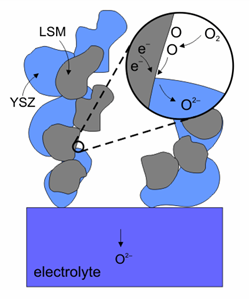
The cathode material is very important because the oxidation reaction determines the efficiency of the fuel cell. Since cathodes operate in a highly oxidising environment, it is impossible to use cheap base metals. The best compromise is semiconducting oxides, such as doped lanthanum cobaltites and lanthanum manganites. A new material: La0.8Sr0.2MnO3 (LSM) has the suitable properties: good electronic conductivity and matching heat expansion coefficient. Since the operating temperature of the fuel cells was reduced to below 1000 °C, it is possible to mix LSM with YSZ at 50/50 proportion to form the first surface on the electrolyte. Other materials have been used, such as La0.6Sr0.4Co0.2Fe0.8O3 (LSCF). LSCF has the advantage of lower power losses at lower temperatures and less susceptibility to poisoning by chromium and it is used with ceria based electrolytes.

Reduction reaction on the surface of a cathode made of LSM-YSZ.(Image courtesy of Risø National Laboratory)
The loss of cathode performance is mainly due to changes in the microstructure and the phase composition of the material at load conditions. If stainless steel interconnects are used, degradation caused by Cr poisoning occurs, since it evaporates from the steel and condensates preferably on the cathode. In general, the rate at which Cr poisoning occurs decreases with decreasing operating temperature.

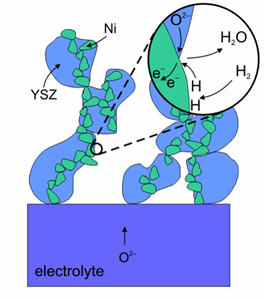
Oxidation reaction on the surface of an anode made of Ni-YSZ (Image courtesy of Risø National Laboratory)
Nickel is used as the anode because it is economical and exhibits high performance, although due to reasons of adherence and different expansion coefficients, it flakes off easily from the electrolyte unless it is mixed with zirconia, creating a cermet. Ni-YSZ anode allows a rapid and clean connection with the fuel and is a good electronic conductor although Ni is susceptible to become coated with a carbon layer when it is reacting with carbon based fuels, which could prevent further reaction. Certain additives to the Ni+YSZ cermet, such as 5% ceria or 1% molybdena inhibit this process. Besides catalysing the oxidation of hydrogen, Ni is also active in reforming of carbon containing fuels. Anodes, completely made of ceramics show good oxidation-reduction cyclability.

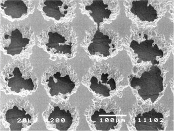
Scanning electron micrograph showing a nickel anode
The contact sides of the electrolyte with the fuel and the oxidant are coated with the electrode material. To form porous contact layers, partially sintered materials are used and to allow a gradient of properties, such as heat expansion coefficient several layers with different compositions are laid down. Since the gas atoms discharge (or absorb) electrons at the anode (or cathode), a three-phase boundary zone is required:
- Gas phase (high porosity of electrolyte required for better access)
- Electrolyte phase for ion transport
- Metal phase for electron conduction
Hence a volumetric three dimensional region has to be provided for the reaction. The most common methods of applying the electrode layer on the electrolyte are plasma spraying, vapour deposition, solution coating and colloidal ink methods.


