
12.4: Modification of Member Stiffness
- Page ID
- 43001

Case 1: A beam hinged at one end and fixed at the other
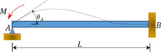
\(Fig. 12.4\). Beam
Consider a beam hinged at end \(A\) and fixed at end \(B\), as shown in Figure 12.4. Applying a moment \(M\) rotates the hinge end by an amount \(\theta\). Writing the slope-deflection equation for the end \(A\) of the member and noting that \(\theta_{B}=\psi_{A B}=M_{A B}^{F}=0\) suggests the following: \[\begin{aligned}
M_{A B} &=\frac{2 E I}{L}\left(2 \theta_{A}+\theta_{B}-3 \psi_{A B}\right)+M_{A B}^{F} \\
&=\frac{2 E I}{L}\left(2 \theta_{A}+0-0\right)+0 \\
M_{A B} &=\left(\frac{4 E I}{L}\right) \theta_{A}
\end{aligned}\]
By definition, the bending stiffness of a structural member is the moment that must be applied to an end of the member to cause a unit rotation of that end. The following expression for the bending stiffness for the member with a fixed far end is expressed as follows when substituting \(\theta_{A}=1\) into equation 12.7: \[K=\frac{4 E I}{L}\]
By definition, the relative bending stiffness of a member is determined by dividing the bending stiffness of the member by \(4E\). Dividing the equation 12.8 by \(4E\) suggests the following expression for relative stiffness for the case being considered: \[K_{R}=\frac{4 E I}{4 E L}=\frac{I}{L}\]
Case 2: A beam hinged at both ends
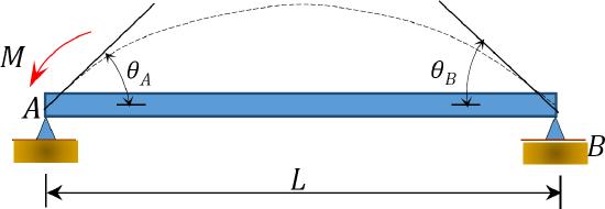
\(Fig. 12.5\). Simply supported beam.
Applying a moment \(M\) at the end \(A\) of the simply supported beam shown in Figure 12.5 rotates the beam by an angle \(\theta_{A}\) at the hinged end. Using the modified slope-deflection equation derived in section 11.4 of Chapter 11 and noting that \(\psi=M_{A B}^{F}=M_{B A}^{F}=0\) suggests the following expression for the moment at the hinged end where the load is applied: \[\begin{array}{l}
M_{A B}=\frac{3 E I}{L}\left(\theta_{A}-\psi\right)+\left(M_{A B}^{F}-\frac{M_{B A}^{F}}{2}\right) \\
=\frac{3 E L}{L}\left(\theta_{A}-0\right)+(0-0) \\
M_{A B}=\left(\frac{3 E I}{L}\right) \theta_{A}
\end{array}\]
Substituting \(\theta_{A}=1\) into equation 12.10 suggests the following expression for the bending stiffness for a member with a hinged far end: \[K=\frac{3 E I}{L}\]
The relative stiffness for a member with a hinged far end is obtained by dividing equation 12.11 by \(4E\), as follows: \[K_{R}=\frac{3 E I}{4 E L}=\frac{3}{4}\left(\frac{I}{L}\right)\]
Comparing equations 12.12 and 12.9 suggests that a member with a hinged far end is three-fourth as stiff as a member with the same geometry but fixed at the far end. This established fact can substantially reduce the number of iteration when analyzing beams or frames with a hinged far end using the method of moment distribution. In such cases, the relative stiffness of the beam at the near end is first adjusted according to equation 12.12, and its distribution factor is computed with the adjusted stiffness. During the balancing operation, the near end will be balanced just once with no further carrying over of moments from or to its end.