
3.3: Forward Kinematics using the Denavit-Hartenberg scheme
- Page ID
- 14783

So far, we have considered the forward kinematics of wheeled mechanisms and simple arms and derived relationships between actuator parameters and velocities using basic trigonometry. In the specific case of multi-link arms, we can also think about the forward kinematics as a chain of homogenous transformations with respect to a coordinate system mounted at the base of a manipulator or a fixed position in the room. Deriving these transformations can be confusing and can be facilitated by following a “recipe” such as conceived by Denavit and Hartenberg. The so-called Denavit-Hartenberg (DH) scheme has evolved as quasi-standard and can easily be automatized, i.e., applied to a 3D model of a robotic arm, e.g.
A manipulating arm consists of links that are connected by joints. Joints can be either rotational or prismatic, i.e., change their length and thus providing additional degrees of freedom. Knowing the length of all rigid links, the position of the manipulators end-effector is fully described by its joint angles and joint offset (for prismatic joints).
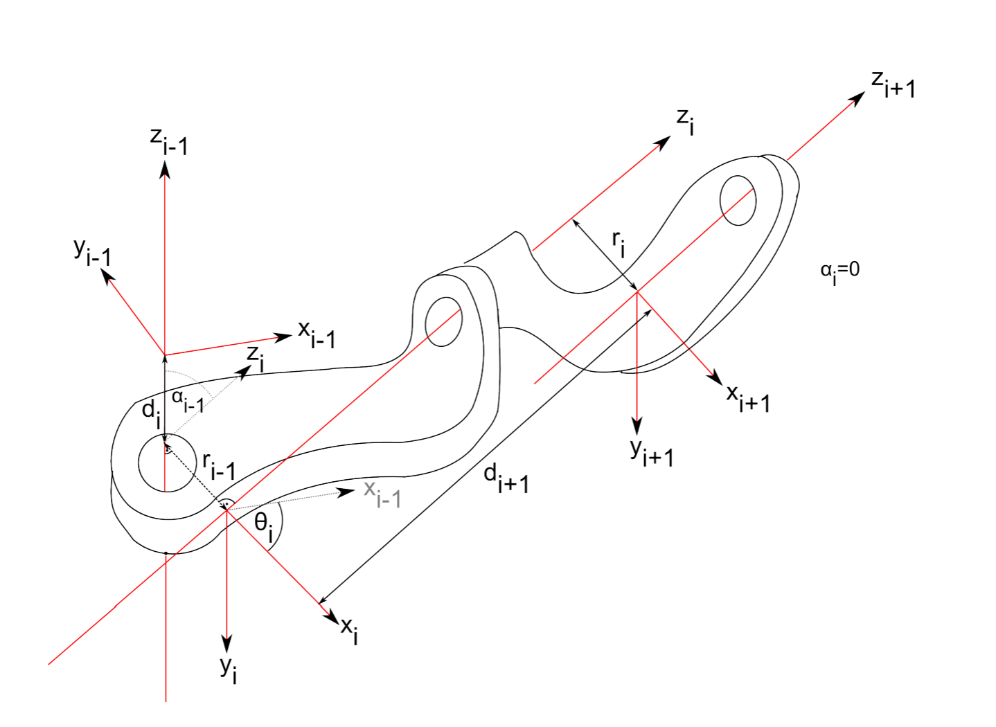
In order to use the DH-convention, we first need to define a coordinate system at each joint. We chose the z-axis to be the axis of rotation for a hinge joint and the axis of translation for a prismatic joint. We can now find the common normal between the z-axes of two subsequent joints, i.e., a line that is orthogonal to each z-axis and intersects both. With the direction of the x-axis at the base arbitrary, subsequent x-axis are chosen such that they lie on the common normal shared between two joints. Whereas the direction of the z-axis is given by the positive direction of rotation (right-hand rule), the x-axis points away from the previous joint. This allows defining the y-axis using the right-hand rule. Note that these rules, in particular the requirement that x-axes lie along the commom normal, might result in coordinate systems with their origins outside the joint.
The transformation between two joints is then fully described by the following four parameters:
- The length r of the common normal between the z-axes of two joints i and i − 1 (link length).
- The angle α between the z-axes of the two joints with respect to the common normal (link twist), i.e., the angle between the old and the new z-axis, measured about the common normal.
- The distance d between the joint axes (link offset), i.e., the offset along the previous z-axis to the common normal.
- The rotation θ around the common axis along which the link offset is measured (joint angle), i.e., the angle from the old x-axis to the new x-axis, about the previous z-axis.
Two of the D-H parameters describe the link between the joints, and the other two describe the link’s connection to a neighboring link. Depending on the link/joint type, these numbers are fixed or can be controlled. For example, in a revolute joint θ is the varying joint angle, while all other quantities are fixed. Similarly, for a prismatic joint d is the joint variable. An example of two revolute joints is shown in Figure 3.3.1.
The coordinate transform from one link (i−1) to another (i) can now be constructed using the following matrix:
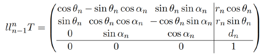
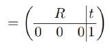
with the rotation matrix R and the translation vector t. This matrix can be constructed by a series of rotations and translations, one for each DH parameter:
\[_{n-1}^{n}\textrm{T}=T_{z}^{'}(d_{n})R_{z}^{'}(\theta _{n})T_{x}(r_{n})R_{x}(\alpha _{n})\]
with
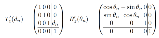
and
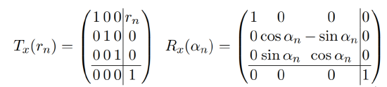
These are a translation of dn along the previous z-axis (T'z (dn)), a rotation of θn about the previous z-axis (R'z (θn)), a translation of rn along the new x-axis (Tx(rn))and a rotation of αn around the new x-axis (Rx(αn)).
Like for any homogeneous transfrom, the inverse n−1nT−1n is given by
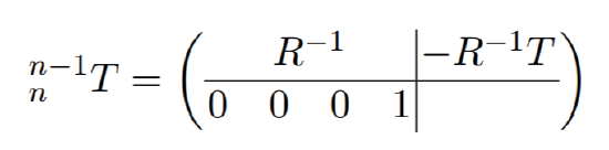
with the inverse of R simply being its transpose.