
10.2: Simple Grasping Mechanisms
- Page ID
- 14831

Understanding why grasping actually works, namely due to friction and increasing contact area due to deformation, allows us to select grasping mechanism that are both able to successfully grasp a wide range of objects, simple to construct, and easy to control. Here, properties of interest are the range of possible object sizes, given by a minimum and maximum size, the maximum weight of an object, and how fragile objects can possibly be. Here, object dimensions are directly dependent on the gripper kinematics, such as minimum and maximum aperture, whereas the maximum weight is given by the torque the mechanism can exert as well as the number of contacts and their friction parameters. Whether a gripper can handle fragile objects, is a function of how well this torque can be measured and controlled.
10.2.1. 1-DoF Scissor-Like Gripper
One of the simplest grippers is a simple one degree-of-freedom claw, which is a popular design in the prosthetic community, and has been refined for centuries. Actuated by a string mounted to a person’s shoulder, or more recently by electric motors controlled by measuring muscle activity in the lower arm, this simple mechanism enables their wearers to perform a wide range of everyday activities. Indeed, an off-the-shelf prosthetic hand has been shown to perform a large variety of grasping and manipulation tasks when compared with other robotic hands in a tele-operation scenarior, only limited by its ability to conform to specific kinematic constraints such as operating scissors (Patel, Segil & Correll 2016).
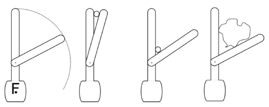
A simple design is shown in Figure 10.2.1 and consists of an active finger that presses an object against a passive finger, with both fingers often shaped as a hook. As should be clear by now, such a design can only work by relying on friction, which makes it not very common in traditional robotics.
The key advantage of this mechanism is the very simple control strategy that it enables: use the passive finger to make contact with the object, then use the active finger to close the grasp. The event “make contact” can either be detected by measuring the force at the wrist and looking for abrupt changes or using a tactile sensor on the surface with which contact is made. This approach can therefore lead to robust grasps with a minimum of sensing. A disadvantage of this mechanism is that its function relies exclusively on friction, possibly ejecting objects from its grasp if friction is not sufficient or the object is in an otherwise suboptimal conformation. Unlike most other mechanisms, it is also impossible to use the finger position to infer the width of an object, which is illustrated by the illustrations in Figure 10.2.1, center.
The mechanism shown in Figure 10.2.1 can be actuated in many different ways, for example by attaching a servo motor directly to the active finger, using a shape-memory alloy wire via a suitable lever arm, or a pneumatic piston or balloon.
10.2.2. Parallel Jaw
The most common industrial mechanism is the two-finger parallel jaw gripper. It operates by squeezing an object between its two parallel jaws, which are usually driven by a single actuator and therefore move in concert. Parallel jaw grippers usually yield more contact area than a scissor-like 1-DoF gripper, but suffer from a smaller range of motion.
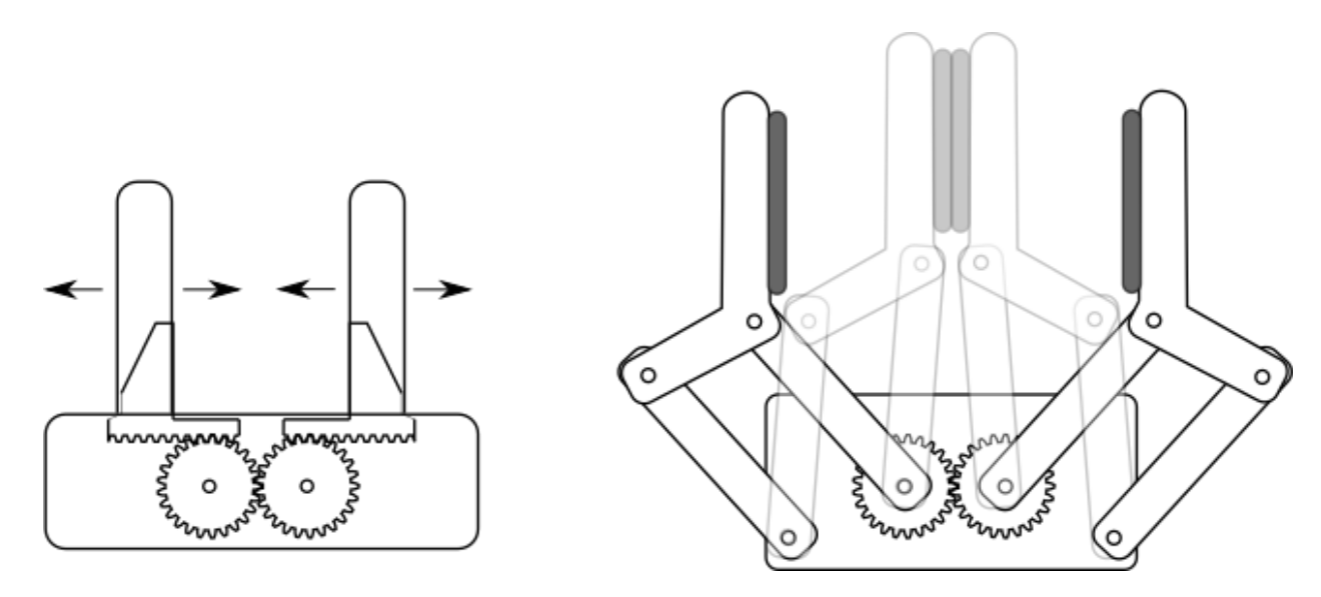
Figure 10.2.2, left, shows a minimalist implementation of a parallel jaw gripper that can be actuated by a single servo motor, driving two rack gears to which the gripper jaws are mounted. While using gears on racks is unusual in an industrial design — the gripper jaws typically travel on threads actuated by worm gears or are attached to a pneumatic piston — this drawing illustrates the relationship between the range of motion of the gripper jaws, the length of the mechanism it is sliding on, here a rack gear, and the resulting body size. In order for this design to fully close, the two rack gears must be mounted at an offset in order to slide against each other. Constraints like this often make the gripper body twice as wide as the maximum aperture, making it difficult for the robot to enter tight areas. The mechanical design also affects the speed at which a gripper can operate. Pneumatic grippers, where air pressure coming in on either end of the piston can drive the gripper into an “open” or “close” position very quickly (2-3 times per second), but cannot be controlled accurately. Electric mechanisms instead trade accuracy and torque with speed.
The control strategy for parallel jaw grippers requires an accurate pose estimate of the object of interest and positioning the gripper so that the object is right in the center of the two jaws. Note that force-closure with a static object, such as a screw mounted to a structure, requires both jaws to make contact with the object at the same time, thereby imposing high accuracy requirements of both object detection and robot motion. Here, compliance can help, allowing the gripper to adjust its pose to the object. This can be accomplished by either measuring forces in the wrist and moving the gripper to minimize lateral forces or a compliant mounting mechanism or structure, such as a robot equipped with series-elastic or pneumatic actuators. An alternative approach is to actuate both gripper jaws independently.
10.2.3. 4-Bar Linkage Parallel Gripper
A parallel jaw mechanism with a larger range of motion can be accomplished using two 4-bar linkages, Figure 10.2.2, right. In a 4-bar linkage, rotation is translated into straight translation. This is accomplished by two pairs of parallel bars of equal lengths. In Figure 10.2.2, right, one of the four bars is not moving and substituted by the gripper body, to which two of the bars are mounted. Interestingly, both pairs remain parallel as one of the bars is rotating, resulting in the two gripper jaws remaining parallel to each other. This is best understood by inspecting Figure 10.2.2 and comparing the two positions the left jaw can be in.
The drawback of this design is that closing the gripper also results in a forward motion. This requires approaching an object from different heights, depending on its width. Other than this, the control strategy is the same as for the parallel jaw gripper, requiring an accurate estimate of the object’s pose. Also here, adding compliance or independent actuation of each jaw can help resolving accuracy problems.
10.2.4. Multi-Fingered Hands
Grippers with more than two fingers/jaws are rarely used in industrial practice. One common use case is grasping cylindrical objects from above, for which three-fingered hands, such as indicated in Figure 10.1.1, right, are best suited. In most other cases, three fingers are not an advantage, and might even be a hindrance, however. For example, it is difficult to perform simple pinching grasps with three fingers. This has led to designs in which two of the fingers are reconfigurable from performing an inwards motion to behave identical to a parallel jaw gripper, while the third finger is stored in a safe position. In addition to mechanical complexity, such an approach requires also additional planning steps.
How many grasps are possible and how many possible grasps are needed to grasp every possible object remains a difficult theoretical problem (which is further complicated by the fact that successful grasping often happens at the boundary of what is mathematically tractable). Generally, we can say however, that additional fingers — such as in the human hand — provide additional redundancy, which allows grasping and manipulating (see Section 10.4) the same object in many different ways, including manipulating the object within the hand, that is without intermettent placement or handing it over to another gripper.