
Chapter 3: Defects in Crystalline Materials
- Page ID
- 97980

\( \newcommand{\vecs}[1]{\overset { \scriptstyle \rightharpoonup} {\mathbf{#1}} } \)
\( \newcommand{\vecd}[1]{\overset{-\!-\!\rightharpoonup}{\vphantom{a}\smash {#1}}} \)
\( \newcommand{\dsum}{\displaystyle\sum\limits} \)
\( \newcommand{\dint}{\displaystyle\int\limits} \)
\( \newcommand{\dlim}{\displaystyle\lim\limits} \)
\( \newcommand{\id}{\mathrm{id}}\) \( \newcommand{\Span}{\mathrm{span}}\)
( \newcommand{\kernel}{\mathrm{null}\,}\) \( \newcommand{\range}{\mathrm{range}\,}\)
\( \newcommand{\RealPart}{\mathrm{Re}}\) \( \newcommand{\ImaginaryPart}{\mathrm{Im}}\)
\( \newcommand{\Argument}{\mathrm{Arg}}\) \( \newcommand{\norm}[1]{\| #1 \|}\)
\( \newcommand{\inner}[2]{\langle #1, #2 \rangle}\)
\( \newcommand{\Span}{\mathrm{span}}\)
\( \newcommand{\id}{\mathrm{id}}\)
\( \newcommand{\Span}{\mathrm{span}}\)
\( \newcommand{\kernel}{\mathrm{null}\,}\)
\( \newcommand{\range}{\mathrm{range}\,}\)
\( \newcommand{\RealPart}{\mathrm{Re}}\)
\( \newcommand{\ImaginaryPart}{\mathrm{Im}}\)
\( \newcommand{\Argument}{\mathrm{Arg}}\)
\( \newcommand{\norm}[1]{\| #1 \|}\)
\( \newcommand{\inner}[2]{\langle #1, #2 \rangle}\)
\( \newcommand{\Span}{\mathrm{span}}\) \( \newcommand{\AA}{\unicode[.8,0]{x212B}}\)
\( \newcommand{\vectorA}[1]{\vec{#1}} % arrow\)
\( \newcommand{\vectorAt}[1]{\vec{\text{#1}}} % arrow\)
\( \newcommand{\vectorB}[1]{\overset { \scriptstyle \rightharpoonup} {\mathbf{#1}} } \)
\( \newcommand{\vectorC}[1]{\textbf{#1}} \)
\( \newcommand{\vectorD}[1]{\overrightarrow{#1}} \)
\( \newcommand{\vectorDt}[1]{\overrightarrow{\text{#1}}} \)
\( \newcommand{\vectE}[1]{\overset{-\!-\!\rightharpoonup}{\vphantom{a}\smash{\mathbf {#1}}}} \)
\( \newcommand{\vecs}[1]{\overset { \scriptstyle \rightharpoonup} {\mathbf{#1}} } \)
\(\newcommand{\longvect}{\overrightarrow}\)
\( \newcommand{\vecd}[1]{\overset{-\!-\!\rightharpoonup}{\vphantom{a}\smash {#1}}} \)
\(\newcommand{\avec}{\mathbf a}\) \(\newcommand{\bvec}{\mathbf b}\) \(\newcommand{\cvec}{\mathbf c}\) \(\newcommand{\dvec}{\mathbf d}\) \(\newcommand{\dtil}{\widetilde{\mathbf d}}\) \(\newcommand{\evec}{\mathbf e}\) \(\newcommand{\fvec}{\mathbf f}\) \(\newcommand{\nvec}{\mathbf n}\) \(\newcommand{\pvec}{\mathbf p}\) \(\newcommand{\qvec}{\mathbf q}\) \(\newcommand{\svec}{\mathbf s}\) \(\newcommand{\tvec}{\mathbf t}\) \(\newcommand{\uvec}{\mathbf u}\) \(\newcommand{\vvec}{\mathbf v}\) \(\newcommand{\wvec}{\mathbf w}\) \(\newcommand{\xvec}{\mathbf x}\) \(\newcommand{\yvec}{\mathbf y}\) \(\newcommand{\zvec}{\mathbf z}\) \(\newcommand{\rvec}{\mathbf r}\) \(\newcommand{\mvec}{\mathbf m}\) \(\newcommand{\zerovec}{\mathbf 0}\) \(\newcommand{\onevec}{\mathbf 1}\) \(\newcommand{\real}{\mathbb R}\) \(\newcommand{\twovec}[2]{\left[\begin{array}{r}#1 \\ #2 \end{array}\right]}\) \(\newcommand{\ctwovec}[2]{\left[\begin{array}{c}#1 \\ #2 \end{array}\right]}\) \(\newcommand{\threevec}[3]{\left[\begin{array}{r}#1 \\ #2 \\ #3 \end{array}\right]}\) \(\newcommand{\cthreevec}[3]{\left[\begin{array}{c}#1 \\ #2 \\ #3 \end{array}\right]}\) \(\newcommand{\fourvec}[4]{\left[\begin{array}{r}#1 \\ #2 \\ #3 \\ #4 \end{array}\right]}\) \(\newcommand{\cfourvec}[4]{\left[\begin{array}{c}#1 \\ #2 \\ #3 \\ #4 \end{array}\right]}\) \(\newcommand{\fivevec}[5]{\left[\begin{array}{r}#1 \\ #2 \\ #3 \\ #4 \\ #5 \\ \end{array}\right]}\) \(\newcommand{\cfivevec}[5]{\left[\begin{array}{c}#1 \\ #2 \\ #3 \\ #4 \\ #5 \\ \end{array}\right]}\) \(\newcommand{\mattwo}[4]{\left[\begin{array}{rr}#1 \amp #2 \\ #3 \amp #4 \\ \end{array}\right]}\) \(\newcommand{\laspan}[1]{\text{Span}\{#1\}}\) \(\newcommand{\bcal}{\cal B}\) \(\newcommand{\ccal}{\cal C}\) \(\newcommand{\scal}{\cal S}\) \(\newcommand{\wcal}{\cal W}\) \(\newcommand{\ecal}{\cal E}\) \(\newcommand{\coords}[2]{\left\{#1\right\}_{#2}}\) \(\newcommand{\gray}[1]{\color{gray}{#1}}\) \(\newcommand{\lgray}[1]{\color{lightgray}{#1}}\) \(\newcommand{\rank}{\operatorname{rank}}\) \(\newcommand{\row}{\text{Row}}\) \(\newcommand{\col}{\text{Col}}\) \(\renewcommand{\row}{\text{Row}}\) \(\newcommand{\nul}{\text{Nul}}\) \(\newcommand{\var}{\text{Var}}\) \(\newcommand{\corr}{\text{corr}}\) \(\newcommand{\len}[1]{\left|#1\right|}\) \(\newcommand{\bbar}{\overline{\bvec}}\) \(\newcommand{\bhat}{\widehat{\bvec}}\) \(\newcommand{\bperp}{\bvec^\perp}\) \(\newcommand{\xhat}{\widehat{\xvec}}\) \(\newcommand{\vhat}{\widehat{\vvec}}\) \(\newcommand{\uhat}{\widehat{\uvec}}\) \(\newcommand{\what}{\widehat{\wvec}}\) \(\newcommand{\Sighat}{\widehat{\Sigma}}\) \(\newcommand{\lt}{<}\) \(\newcommand{\gt}{>}\) \(\newcommand{\amp}{&}\) \(\definecolor{fillinmathshade}{gray}{0.9}\)“Crystals are like people, it is the defects in them which tend to make them interesting! - Professor Sir Colin Humphreys”
A crystal is at a state of thermodynamic equilibrium when its free energy G = H − TS is minimized. When are we (humans) at equilibrium?
We have two knobs that we can tune to lower the free energy of the system above and that is entropy and enthalpy. At low temperatures our entropy knob becomes negligible and energy is minimized by minimizing H. This is done via binding and forming the ordered structures that we discussed previously. At the limit of T = 0 that perfect crystal is the equilibrium configuration. When temperature increases the free energy is minimized by adopting a less well ordered atomic/molecular arrangement because that increases the entropy. Entropy increases when imperfections exist so when the temperature is not zero the equilibrium state will most likely contain imperfections. We can calculate the equilibrium concentration by looking at the change in free energy \(\Delta G\)and the \(\Delta S\) by adding imperfections and the enthalpic \(\Delta H_f\) cost of forming those defects.
3.1 Crystalline Point Defects (0D)
I have recorded a series of videos to supplement this text which can be found in the playlist below:
https://www.youtube.com/playlist?lis...0gUPDmo3Kg69Tr
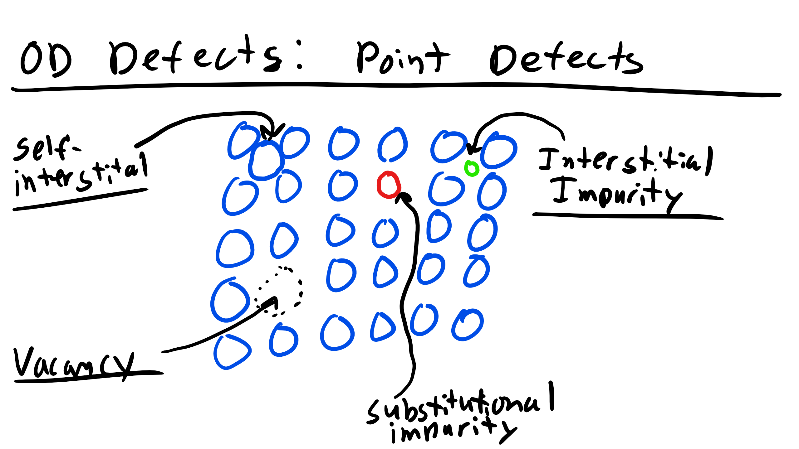
3.1.1 Vacancies
A vacancy exists when a site that is normally occupied in the perfect crystal is unoccupied. This can occur in many ways for example, forcing an atom onto an interstitial site, into a dislocation core, or to a grain boundary or free surface. You can see a couple of examples of a vacancy below
We can actually calculate the equilibrium concentration of vacancies, n! Consider a reference state of a perfect crystal of N atoms and a continuous set of vacancies, n. The new state is a crystal containing a mixture of N atoms and vacancies. The total enthalpy change is then
\begin{equation}
\Delta H_{f} = n \Delta h_{f}
\end{equation}
where \(\Delta h_f\) is the enthalpy of formation of a single vacancy. We can also get an idea about the change in configurational entropy from creating vacancies if we remember Boltmann’s entropy equation (he had it carved on his tombstone...show off)
\begin{equation}
S = k \ln \Omega_m
\end{equation}
where k is the Boltmann constant and \(\Omega_m\) is the number of distinguishable ways you can arrange the system. The configurational entropy \(\Delta S_c\) is then given by
\begin{equation}
\Delta S_{c} = S_{mix} - S_{ref} = k \ln\bigg(\frac{\Omega_{m}}{\Omega_{ref}}\bigg) = k \ln \Omega_{m} = k \ln \frac{(N +n)!}{N!n!}
\end{equation}
where \(\Omega_m\) is the number of distinguishable ways of arranging N atoms an n vacancies on N+n sites and \(\Omega_{ref}\) is the number of configurations in the ideal reference state, which is 1 since there are no defects. So the total Gibbs energy change is
\begin{equation}
\Delta G = \Delta H - T \Delta S = n(\Delta h_{f} - T\Delta S_{v}) - kT[(N+n)\ln(N+n) - N \ln N - n \ln n]
\end{equation}
where \(\Delta S_v\)is the vibrational entropy of the atoms surrounding the vacancy and we used Sterlin’s approximation \(\ln X! \approx X \ln X - X\) to get to the equation above. Now how do we minimize Gibbs? Well we take the derivative and set it equal to zero:
\begin{equation}
\frac{\partial \Delta G}{\partial n} = \Delta h_{f} - T \Delta s_{v} + kT \ln \frac{n}{n + N} = 0
\end{equation}
We can now solve for the equilibrium fraction of vacant sites \(x_v\)
\begin{equation}
x_{v} = \frac{n}{n + N} = \exp\bigg(\frac{\Delta s_{v}}{k}\bigg)\exp\bigg(-\frac{\Delta h_{f}}{kT}\bigg)
\end{equation}
You should notice in this equation that there is an exponential temperature dependence, known as Arrhenius dependence or Arrhenius’s law. This is critical because there are many behaviors in Materials Science which are Arrhenius. Let’s take a look at how strongly the concentration of vacancies varies with temperature by looking an example Arrhenius plot below
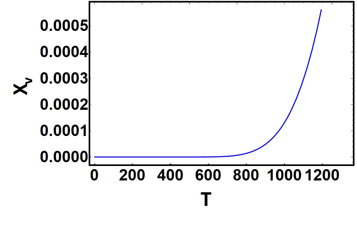
Now typically we can assume that the \(\exp (\frac{\Delta S_{v}}{k}) \approx 1\). The enthalpy of formation of vacancies for metals is typically on the order of 15-150kT (kT = 0.026 eV) So we can clearly see that at room temperature the probability of forming vacancies will be pretty low already. Is this supported by the graph?
This method is not the typical way Arrhenius graphs are presented. It is actually better to plot the Log of the equilibrium concentration of vacancies as a function of the reciprocal temperature \(\frac{1}{T}\) That way we can extract the activation energy or energy of formation of the vacancy.
3.1.2 Interstitals
An interstital defect occurs when an atom occupies an interior site which is not normally occupied. If the interstital is of the same species in a single component crystal it is a self-interstital and we have the following equation for the equilibrium number of self-interstitals
\begin{equation}
x_{i} = \frac{n}{n + N} = \exp\bigg(\frac{\Delta s_{v}}{k}\bigg)\exp\bigg(-\frac{\Delta h_{f}}{kT}\bigg)
\end{equation}
however now the \(\Delta s_v\) and \(\Delta h_f\) represent the enthalpy of formation and vibrational entropy for interstitial formation. As you might imagine the energy of formation for interstitial is lower for more open an less densely packed structures. Obviously there are also higher numbers of these 0D defects for nonequilibrium processes like quenching, irradiation, ion implantation, or cold working.
3.1.3 Alloys
An alloy is formed when one or more species is mixed to form a solid or liquid solution (brass, Ti-64, stainless steel, etc.) The major component is the solvent and the minor component is the solute.[1] When the solute occupies sites normally unoccupied by the solvent in the crystal then it is an interstitial solid solution. If the solute occupies a site normally occupied by the solvent then the crystal is a substitutional solid solution. Typically alloys should have
1. Atomic radii differences of ±15%
2. Same crystal structure
3. Maximum allowable concentration of interstitial impurities less than 10%.
Just for definition’s sake to calculate weight percent (wt%) it is simply
\begin{equation}
WT\% = \frac{m_{A}}{m_{A}+m_{B}} \times 100
\end{equation}
where \(m_a\) is the mass of component A and \(m_b\) is the mass of component B. And atomic percent (at%) is simply the number of moles of one element over the total number of moles in the alloy.
3.2 Point Defects, Kroger-Vink Notation, and Schottky and Frenkel Defects
Point defects in ionically boned crystals typically have an associated charge. Now the net charge of a perfect crystal is zero. Cations have lost one or more electrons and thus have a net positive charge. Anions have gained one or more electrons and thus have a net negative charge. A cation vacancy is created by removing a cation from a site in the crystal to a site on the surface. This vacant site then has a net negative charge. An anion vacancy is created by removing an anion site in the crystal to a site on the surface and the vacant site then has a net positive charge.
Now the way we describe these point defects is by using Kroger-Vink notation and schematically it is represented by:
\begin{equation}
X^{Z}_{Y}
\end{equation}
where X represents what is on the site: either V for a vacancy or if occupied by an element, the element symbol. Y represents what type of site is occupied by X, either i for interstitial or if normally occupied by an element the symbol for that element. Z represents the charge relative to the normal ion charge on the site Y using dots to represent positive relative charges, primes to indicate negative relative charges, and x to indicate zero relative charge.
There are two idealized forms of charge-compensating point defects which are the Schottky and Frenkel Defects.
A Schottky defect consists of charge-compensating anion and cation vacancies[2]. Let’s consider KCl for example. What is a Schottky defect? Well it would be
\begin{equation}
Null \leftrightarrow V^{'}_{K} + V^{.}_{Cl}
\end{equation}
What about TiO2?
\begin{equation}
Null \leftrightarrow V^{''''}_{Ti} + 2V^{..}_{O}
\end{equation}
A Frenkel defect is formed when an ion moves from its normal site in the crystal into a nearby interstitial site, forming a Frenkel pair. Let’s examine the cation Frenkel pair in Li\(_2\)O which is
\begin{equation}
Li^{x}_{Li} = Li^{.}_{i} + V^{'}_{Li}
\end{equation}
and the anion Frenkel pair would be
\begin{equation}
O^{x}_{O} = O^{''}_{i} + V^{..}_{O}
\end{equation}}
What about the cation and anion Frenkel pair in UO2 respectively?
\begin{eqnarray}
U^{x}_{U} = U^{....}_{i} + V^{''''}_{U}\\
O^{x}_{O} = O^{''}_{i} + V^{..}_{O}
\end{eqnarray}
You need to have charge and mass balance in the above equations. Charge balance is attained when the sum of the charges on the right hand side equals the sum of charges on left hand side. Mass balance requires that the total number of ions or atoms of a given species is the same on both sides of the reaction. The equilibrium concentrations of charged Schottky defects and Frenkel defects is:
\begin{equation}
x_{pairs} = \exp \bigg(-\frac{\Delta h_{f}}{2kT}\bigg)
\end{equation}
where the formation enthalpy is for a pair of ions either Schottky or Frenkel pair. Among the myriad of defects there will be a dominant defect, known as an intrinsic defect and typically it will be the one with the lowest enthalpy of formation.
3.3 Impurities in Kroger-Vink
We can also describe how impurities can can induce formation of a variety of point defects using Kroger-Vink notation. Let’s think about CaCl\(_2\) impurities in KCl, specifically via incorporation of Ca onto K sites. We assume that the Cl sites can easily be integrated into the structure provided enough vacancies. So one type of impurity incorporation reaction could be:
\begin{equation}
CaCl_{2} \xleftrightarrow{2KCL} Ca^{.}_{K} + V^{'}_{K} + 2Cl^{x}_{Cl}
\end{equation}
Note that we write 2KCl for mass balance. Another defect could be
\begin{equation}
CaCl_{2} \xleftrightarrow{2KCL} Ca^{..}_{i} + 2V^{'}_{K} + 2Cl^{x}_{Cl}
\end{equation}
where we have Ca inserting into an interstitial site.
Let’s practice with ZrO2 (zirconia) impurities in Y2O3 (yttria), two very important ceramic materials, i.e. yitrium stabilized zirconium bio-engineering mechanical applications[2]. Let’s look again at some possible impurity incorporation reactions
\begin{equation}
3ZrO_{2} \xleftrightarrow{2Y_{2}O_{3}} 3Zr^{.}_{Y} + V^{'''}_Y + 6O^{x}_{O}
\end{equation}
or another reaction
\begin{equation}
3ZrO_{2} \xleftrightarrow{2Y_{2}O_{3}} 3Zr^{....}_{i} + 4V^{'''}_Y + 6O^{x}_{O}
\end{equation}
or yet another reaction
\begin{equation}
2ZrO_{2} \xleftrightarrow{Y_{2}O_{3}} 2Zr^{.}_{Y} + O^{''}_i + 3O^{x}_{O}
\end{equation}
Yes you can expect many questions on this topic!
3.4 Dislocation Defects (1D)
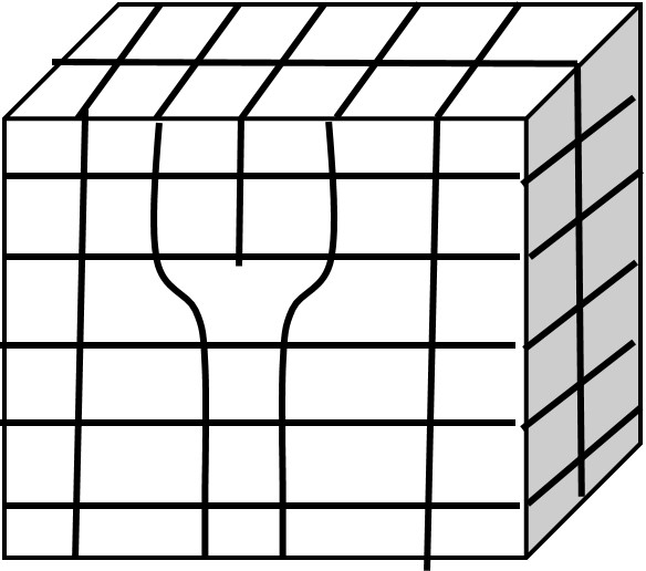
Imperfections that are localized along a space curve passing through an ordered medium are line imperfections. A dislocation is one such defect. A dislocation is a linear or one dimensional line defect which involves translation of one part of a crystal with respect to another part. A disclination involves rotation of one part with respect to another. We will deal with two types of dislocation in this class: edge and screw dislocations.
An edge dislocation is essentially an extra half plane of atoms that is inserted into the perfect crystal and it terminates within the crystal. You can see this below
A screw dislocation is a bit harder to visualize but you can imagine that a screw dislocation can be formed by an applied shear stress, seen below:
You can see that in this example some of the differences between edge and screw dislocations one begin that the screw dislocation motion will be perpendicular to the applied force but more on that in a little bit. There are also wedge and twist disclinations as well.
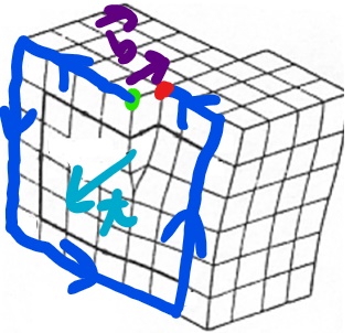
Associated with each dislocation is a dislocation core which is where the largest displacements of atoms from the ideal sites occur and they are concentrated along a dislocation line. We describe dislocations via a unit tangent vector, t, and the Burgers vector, b. The tangent vector is a unit vector that is tangential to the dislocation line at any given point. The Burgers vector, b, is defined in reference to the Burgers circuit. Now in this class we will use the SF/RH (start to finish, right-hand) convention to define the Burgers vector. To define the Burgers vector:
• Choose the positive sense of the unit tangent vector of the dislocation line
• By traveling along rows of lattice points make a right hand circuit in the crystal containing the dislocation. Define a Start Point, S, and Finish Point F.
• This circuit would be a closed circuit in the perfect crystal but in this instance the circuit is only closed by the Burgers vector which connects your Start and Finish points.
A couple of other quick notes about some of the properties of dislocations. It should be noted that the Burgers vector will be conserved and that for a given dislocation there is one constant Burgers vector, even as the tangent vector changes.
• A dislocation cannot end inside a crystal.
• A pure edge dislocation has b perpendicular to t everywhere along the dislocation curve and t × b points toward the extra half plane of atoms
• A pure screw dislocation is either parallel or antiparallel to t everywhere along the dislocation curve. A right-hand screw is parallel and a left-hand screw is anti-parallel.
• A dislocation that is neither pure edge or pure screw is a mixed dislocation and the vector component that is parallel to t is the screw component and the component that is perpendicular to t is called the edge component.
• Reversing the sense of t also reverses the sense of b.
Let’s do an edge dislocation

How about another screw dislocation?
While we are speaking of dislocations one of the key material properties that you will come across is the dislocation density, ρ, which has units of \(m^-{2}\) A highly cold worked material may have a dislocation density of \( 10^{14} m^-{2}\) whereas a highly annealed material can be as low as \(10^7m^-{2}\). Dislocations are additional motile and they can move via slip and climb.
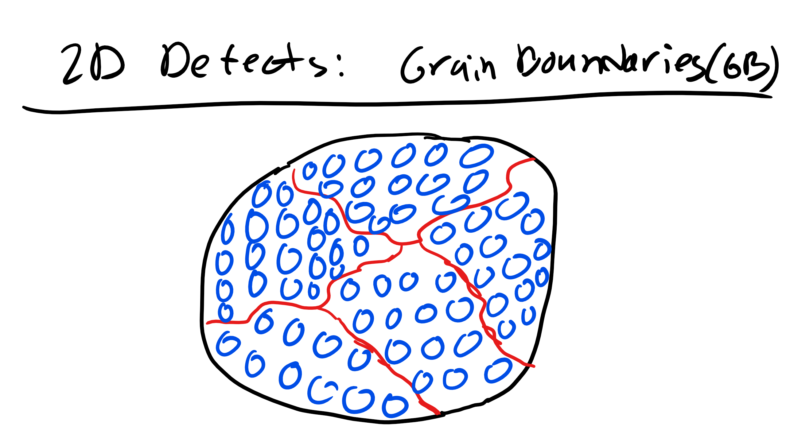
3.5 Grain Boundaries, External Surfaces, Phase Boundaries, Twin Boundaries, and Stacking Faults (2D)
Perhaps the most obvious 2D defect is just an external surface where the bonds at the surface are not satisfied which gives rise to an increase surface energy or surface tension.
Grain Boundaries are interfaces at which crystals of different orientations abut. There are special types of grain boundaries like low angle tilt and twist boundaries when the angle of misorientation of grains is not too large. In fact they are considered simple periodic arrays of dislocations.
Phase boundaries exist in multiphase materials where a different phase exists on each side of the boundary.
A twin boundary is a special type of grain boundary across which there is a specific mirror lattice symmetry. The region of material between these boundaries is a twin. Twins typically appear due to shear stresses or during annealing heat treatments after deformation. Annealing twins are more common in FCC crystals while mechanical twins are more common in BCC and HCP crystals.
Stacking faults are interfaces in crystals across which one part of the crystal is displaced relative to the other part by a displacement vector that is not a translational symmetry operation for that crystal. Remember that for FCC we had this ABCABC stacking and HCP we had ABABAB.
A stacking fault in FCC would be ABCBCABCABC. If the fault is missing a layer that is an intrinsic stacking fault but if there is an extra layer that is an extrinsic stacking fault. Stacking fault energy has severe implications on the strain hardening behavior of materials.
There are also antiphase/interphase boundaries which are separate regions of the crystal by a relative translation that is not a symmetry operation of the crystal. It is a special type of stacking fault, one that connects the crystallographically nonequivalent occupied sites in a perfect crystal. They can be coherent, semi-coherent, incoherent.
3.6 Bulk or Volume Defects (3D)
Finally there are also bulk or volume defects which include pores, cracks, foreign inclusions, and other phases.