
5.1.1: Sources of data
- Page ID
- 78126

\( \newcommand{\vecs}[1]{\overset { \scriptstyle \rightharpoonup} {\mathbf{#1}} } \)
\( \newcommand{\vecd}[1]{\overset{-\!-\!\rightharpoonup}{\vphantom{a}\smash {#1}}} \)
\( \newcommand{\id}{\mathrm{id}}\) \( \newcommand{\Span}{\mathrm{span}}\)
( \newcommand{\kernel}{\mathrm{null}\,}\) \( \newcommand{\range}{\mathrm{range}\,}\)
\( \newcommand{\RealPart}{\mathrm{Re}}\) \( \newcommand{\ImaginaryPart}{\mathrm{Im}}\)
\( \newcommand{\Argument}{\mathrm{Arg}}\) \( \newcommand{\norm}[1]{\| #1 \|}\)
\( \newcommand{\inner}[2]{\langle #1, #2 \rangle}\)
\( \newcommand{\Span}{\mathrm{span}}\)
\( \newcommand{\id}{\mathrm{id}}\)
\( \newcommand{\Span}{\mathrm{span}}\)
\( \newcommand{\kernel}{\mathrm{null}\,}\)
\( \newcommand{\range}{\mathrm{range}\,}\)
\( \newcommand{\RealPart}{\mathrm{Re}}\)
\( \newcommand{\ImaginaryPart}{\mathrm{Im}}\)
\( \newcommand{\Argument}{\mathrm{Arg}}\)
\( \newcommand{\norm}[1]{\| #1 \|}\)
\( \newcommand{\inner}[2]{\langle #1, #2 \rangle}\)
\( \newcommand{\Span}{\mathrm{span}}\) \( \newcommand{\AA}{\unicode[.8,0]{x212B}}\)
\( \newcommand{\vectorA}[1]{\vec{#1}} % arrow\)
\( \newcommand{\vectorAt}[1]{\vec{\text{#1}}} % arrow\)
\( \newcommand{\vectorB}[1]{\overset { \scriptstyle \rightharpoonup} {\mathbf{#1}} } \)
\( \newcommand{\vectorC}[1]{\textbf{#1}} \)
\( \newcommand{\vectorD}[1]{\overrightarrow{#1}} \)
\( \newcommand{\vectorDt}[1]{\overrightarrow{\text{#1}}} \)
\( \newcommand{\vectE}[1]{\overset{-\!-\!\rightharpoonup}{\vphantom{a}\smash{\mathbf {#1}}}} \)
\( \newcommand{\vecs}[1]{\overset { \scriptstyle \rightharpoonup} {\mathbf{#1}} } \)
\( \newcommand{\vecd}[1]{\overset{-\!-\!\rightharpoonup}{\vphantom{a}\smash {#1}}} \)
\(\newcommand{\avec}{\mathbf a}\) \(\newcommand{\bvec}{\mathbf b}\) \(\newcommand{\cvec}{\mathbf c}\) \(\newcommand{\dvec}{\mathbf d}\) \(\newcommand{\dtil}{\widetilde{\mathbf d}}\) \(\newcommand{\evec}{\mathbf e}\) \(\newcommand{\fvec}{\mathbf f}\) \(\newcommand{\nvec}{\mathbf n}\) \(\newcommand{\pvec}{\mathbf p}\) \(\newcommand{\qvec}{\mathbf q}\) \(\newcommand{\svec}{\mathbf s}\) \(\newcommand{\tvec}{\mathbf t}\) \(\newcommand{\uvec}{\mathbf u}\) \(\newcommand{\vvec}{\mathbf v}\) \(\newcommand{\wvec}{\mathbf w}\) \(\newcommand{\xvec}{\mathbf x}\) \(\newcommand{\yvec}{\mathbf y}\) \(\newcommand{\zvec}{\mathbf z}\) \(\newcommand{\rvec}{\mathbf r}\) \(\newcommand{\mvec}{\mathbf m}\) \(\newcommand{\zerovec}{\mathbf 0}\) \(\newcommand{\onevec}{\mathbf 1}\) \(\newcommand{\real}{\mathbb R}\) \(\newcommand{\twovec}[2]{\left[\begin{array}{r}#1 \\ #2 \end{array}\right]}\) \(\newcommand{\ctwovec}[2]{\left[\begin{array}{c}#1 \\ #2 \end{array}\right]}\) \(\newcommand{\threevec}[3]{\left[\begin{array}{r}#1 \\ #2 \\ #3 \end{array}\right]}\) \(\newcommand{\cthreevec}[3]{\left[\begin{array}{c}#1 \\ #2 \\ #3 \end{array}\right]}\) \(\newcommand{\fourvec}[4]{\left[\begin{array}{r}#1 \\ #2 \\ #3 \\ #4 \end{array}\right]}\) \(\newcommand{\cfourvec}[4]{\left[\begin{array}{c}#1 \\ #2 \\ #3 \\ #4 \end{array}\right]}\) \(\newcommand{\fivevec}[5]{\left[\begin{array}{r}#1 \\ #2 \\ #3 \\ #4 \\ #5 \\ \end{array}\right]}\) \(\newcommand{\cfivevec}[5]{\left[\begin{array}{c}#1 \\ #2 \\ #3 \\ #4 \\ #5 \\ \end{array}\right]}\) \(\newcommand{\mattwo}[4]{\left[\begin{array}{rr}#1 \amp #2 \\ #3 \amp #4 \\ \end{array}\right]}\) \(\newcommand{\laspan}[1]{\text{Span}\{#1\}}\) \(\newcommand{\bcal}{\cal B}\) \(\newcommand{\ccal}{\cal C}\) \(\newcommand{\scal}{\cal S}\) \(\newcommand{\wcal}{\cal W}\) \(\newcommand{\ecal}{\cal E}\) \(\newcommand{\coords}[2]{\left\{#1\right\}_{#2}}\) \(\newcommand{\gray}[1]{\color{gray}{#1}}\) \(\newcommand{\lgray}[1]{\color{lightgray}{#1}}\) \(\newcommand{\rank}{\operatorname{rank}}\) \(\newcommand{\row}{\text{Row}}\) \(\newcommand{\col}{\text{Col}}\) \(\renewcommand{\row}{\text{Row}}\) \(\newcommand{\nul}{\text{Nul}}\) \(\newcommand{\var}{\text{Var}}\) \(\newcommand{\corr}{\text{corr}}\) \(\newcommand{\len}[1]{\left|#1\right|}\) \(\newcommand{\bbar}{\overline{\bvec}}\) \(\newcommand{\bhat}{\widehat{\bvec}}\) \(\newcommand{\bperp}{\bvec^\perp}\) \(\newcommand{\xhat}{\widehat{\xvec}}\) \(\newcommand{\vhat}{\widehat{\vvec}}\) \(\newcommand{\uhat}{\widehat{\uvec}}\) \(\newcommand{\what}{\widehat{\wvec}}\) \(\newcommand{\Sighat}{\widehat{\Sigma}}\) \(\newcommand{\lt}{<}\) \(\newcommand{\gt}{>}\) \(\newcommand{\amp}{&}\) \(\definecolor{fillinmathshade}{gray}{0.9}\)Different sources of information are needed for the navigation of an aircraft in the air.
Certain data come by measuring physical magnitudes of the air surrounding the aircraft, such as the pressure (barometric altimeter) or the velocity of air (pitot tube). Other data are obtained by measuring the accelerations of the aircraft using accelerometers. Also the angular changes (changes in attitude) and changes in the angular velocity can be measured using gyroscopes. The course of the aircraft is calculated through the measure of the direction of the magnetic field of the Earth.
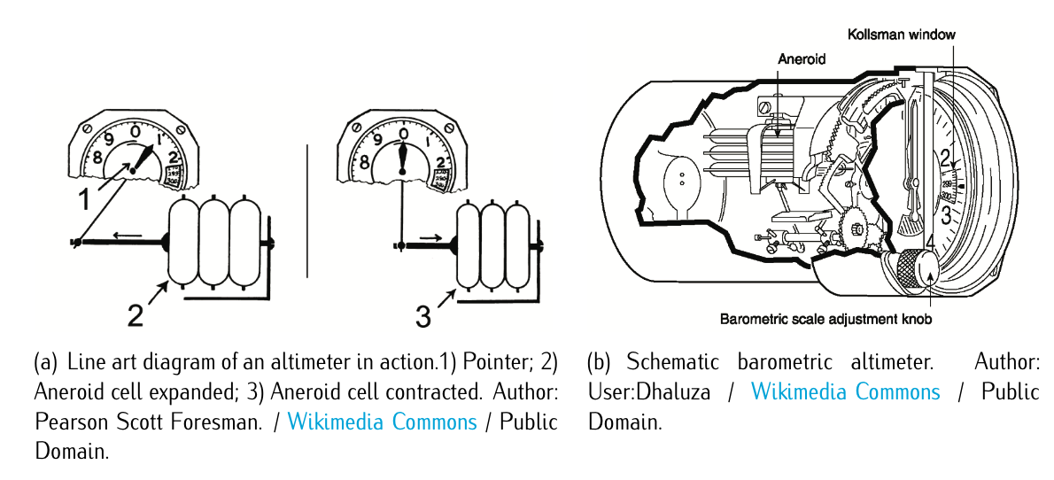
Figure 5.1: Barometric altimeter.
A barometric altimeter is an instrument used to calculate the altitude based on pressure measurements. Figure 5.1 illustrates how a barometric altimeter works and how it looks like. Details on how the altimeter indicator works will be given later on when analyzing the altimeter. Still nowadays, most of the aircraft use the barometric altimeters to determine the altitude of the aircraft. An altimeter cannot, however, be adjusted for variations in air temperature. As already studied in Chapter 2, ISA relates pressure and altitude.
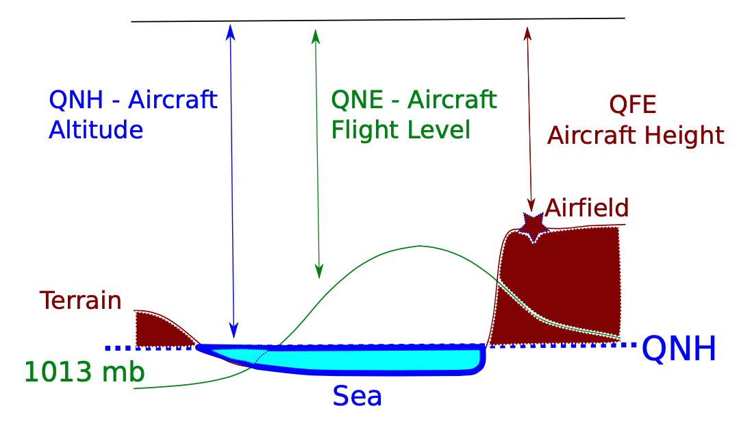
Figure 5.2: Diagram of barometric settings.
Differences in temperature from the ISA model will, therefore, cause errors in the indicated altitude. An aneroid or mercury barometer measures the atmospheric pressure from a static port outside the aircraft and based on a reference pressure. The aneroid altimeter can be calibrated in three manners (QNE, QNH, QFE) to show the pressure directly as an altitude above a reference (101225 [Pa] level, sea level, the airport, respectively). Please, refer to Figure 5.2. Recall Equation (2.3.3.2):
\[\dfrac{p}{p_0} = \left (1 - \dfrac{\alpha}{T_0} h \right )^{\tfrac{g}{R\alpha}}; \ \ \ and\ thus \nonumber \]
\[\dfrac{p_{ref}}{p_0} = \left (1 - \dfrac{\alpha}{T_0} h_{ref} \right )^{\tfrac{g}{R\alpha}}. \nonumber \]
Isolating \(h\) and \(h_{ref}\), respectively, and subtracting, it yields:
\[h - h_{ref} [m] = \dfrac{T_0}{\alpha} \left [ \left (\dfrac{p_{ref}}{p_0}\right )^{\tfrac{g}{R\alpha}} - \left (\dfrac{p}{p_0}\right )^{\tfrac{g}{R\alpha}} \right ]. \nonumber \]
The reference values can be adjusted, and there exist three main standards:
- QNE setting: the baseline pressure is 101325 Pa. This setting is equivalent to the air pressure at mean sea level (MSL) in the ISA.
- QNH setting: the baseline pressure is the real pressure at sea level (not necessarily 101325 [Pa]). In order to estimate the real pressure at sea level, the pressure is measured at the airfield and then, using equation (2.3.3.3), the real pressure at mean sea level is estimated (notice that now \(p_0 \ne 101325\)). It captures better the deviations from the ISA.
- QFE setting: where \(p_{ref}\) is the pressure in the airport, so that \(h - h_{ref}\) reflects the altitude above the airport.
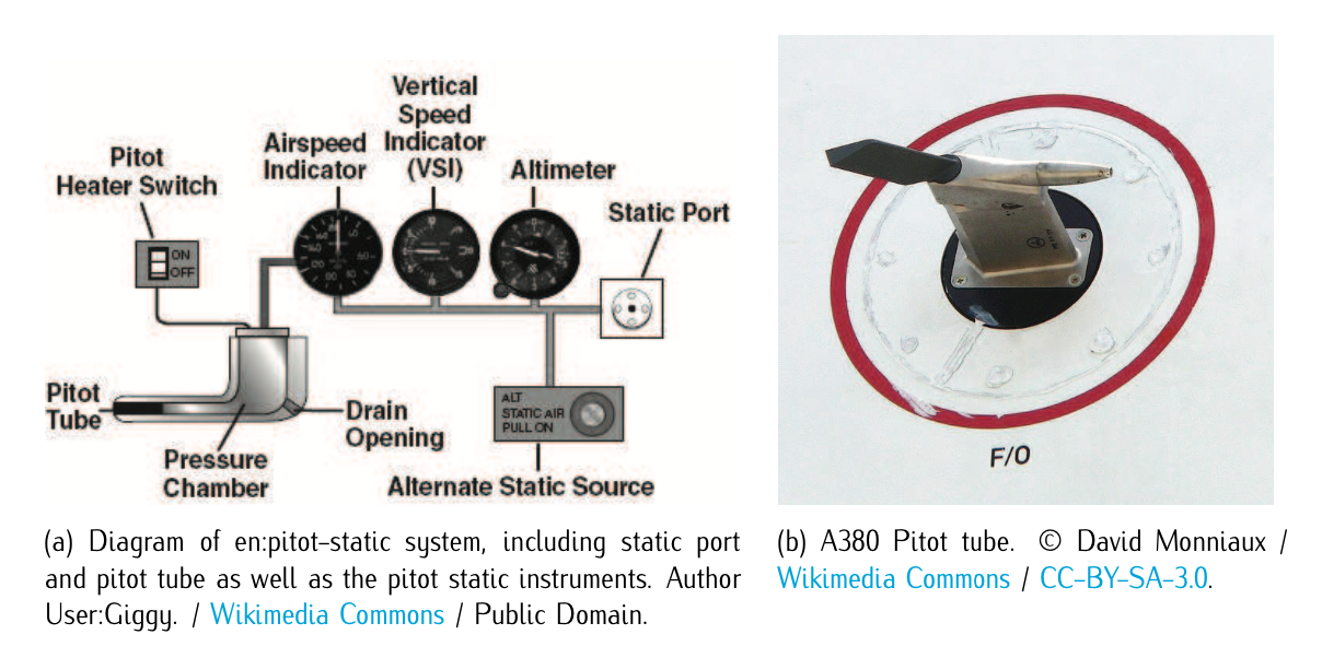
Figure 5.3: Pitot tube.
A pitot tube is an instrument used to measure fluid flow velocity. A basic pitot tube consists of a tube pointing directly into the fluid flow, in which the fluid enters (at aircraft’s airspeed). The fluid is brought to rest (stagnation). This pressure is the stagnation pressure of the fluid, which can be measured by an aneroid. The measured stagnation pressure cannot itself be used to determine the fluid velocity (airspeed in aviation). Using Bernoulli’s equation (see Equation (3.1.3.6)), the velocity of the incoming flow (thus the airspeed of the aircraft, since the pitot tube is attached to the aircraft) can be calculated. Figure 5.3 illustrates how a pitot tube works and how it looks like. Please, refer to Exercise 5.3.1 as an illustration of pitot tube equations. Details on how the airspeed indicator works will be given later on in this chapter.
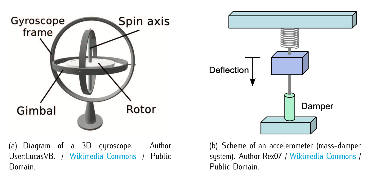
Figure 5.4: Gyroscope and accelerometeres.
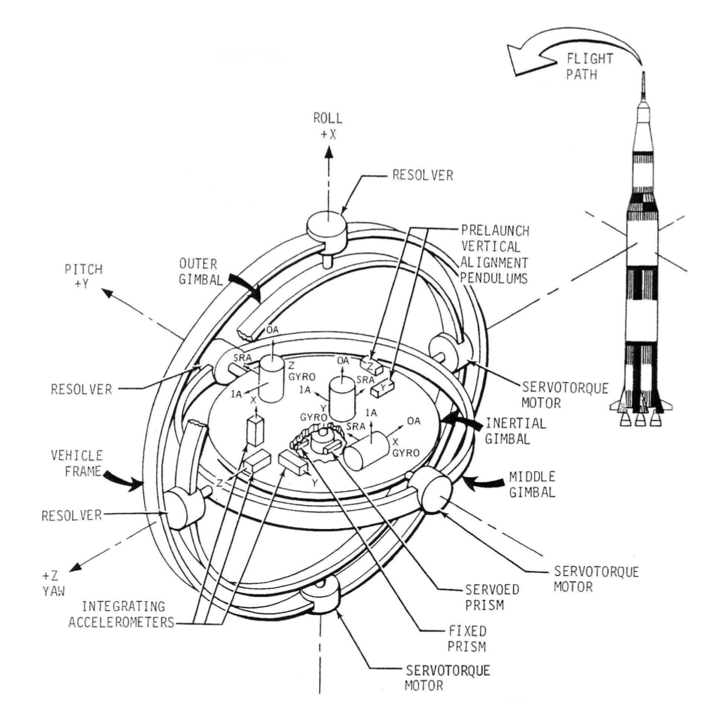
Figure 5.5: Diagram of ST-124 gimbals with accelerometers and gyroscopes (conforming the basic elements of a Inertial Measurement Unit). Author NASA/MSFC / Wikimedia Commons / Public Domain.
A gyroscope is a mechanical (also exist electronic) device based on the conservation of the kinetic momentum, i.e., a spinning cylinder with high inertia rotating at high angular velocity, so that the kinetic momentum is very high and it is not affected by external actions. Thus, the longitudinal axis of the cylinder points always in the same direction. Figure 5.4.a illustrates it. An accelerometer is a device that calculates accelerations based on displacement measurements. It is typically composed by a mass-damper system attached to a spring as illustrated in Figure 5.4.b. When the accelerometer experiences an acceleration, the mass is displaced. The displacement is then measured to give the acceleration (applying basic physics and the Second Newton Law). A typical accelerometer works in a single direction, so that a set of three is needed to cover the three directions of the space. The duple gyroscopes and accelerometer conforms the basis of an Inertial Measurement Unit (IMU), an element used for inertial navigation (to be studied in Chapter 10), i.e., three accelerometers measure the acceleration in the three directions and three gyroscopes measure the angular acceleration in the three axis; with an initial value of position and attitude and via integration, current position, velocity, attitude, and angular velocity can be calculated1. Figure 5.5 illustrates it. See also Exercises 5.3.1-5.3.2 for an insight on IMU usage in the context of Inertial Navigation.
The aircraft can also send electromagnetic waves to the exterior to know, for instance, the altitude with respect to the ground (radio-altimeter), or the presence of clouds in the intended trajectory (meteorologic radar). It can also receive electromagnetic waves from specific aeronautical radio-infrastructures, both for en-route navigation (VOR,2 NDB, etc.), and for approach and landing phases (ILS, MLS, etc). Also, the new systems of satellite navigation (GPS, GLONASS, and the future GALILEO) will be key in the future for more precise and reliable navigation. Aircraft have on-board instruments (the so-called navigation instruments) to receive, process, and present this information to the pilot.
1. Notice that these calculations are complicated, since the values need to be projected in the adequate reference frames, and also the gravity, which is always accounted by the accelerometer in the vertical direction, needs to by considered. This is not covered in this course and will be studied in more advanced courses of navigation.