
2.4: Tolerating Active Faults
- Page ID
- 58500

Responding to Active Faults
In dealing with active faults, the designer of a module can provide one of several responses:
- Do nothing. The error becomes a failure of the module, and the larger system or subsystem of which it is a component inherits the responsibilities both of discovering and of handling the problem. The designer of the larger subsystem then must choose which of these responses to provide. In a system with several layers of modules, failures may be passed up through more than one layer before being discovered and handled. As the number of do-nothing layers increases, containment generally becomes more and more difficult.
- Be fail-fast. The module reports at its interface that something has gone wrong. This response also turns the problem over to the designer of the next higher-level system, but in a more graceful way. Example: when an Ethernet transceiver detects a collision on a frame it is sending, it stops sending as quickly as possible, broadcasts a brief jamming signal to ensure that all network participants quickly realize that there was a collision, and it reports the collision to the next higher level, usually a hardware module of which the transceiver is a component, so that the higher level can consider resending that frame.
- Be fail-safe. The module transforms any value or values that are incorrect to values that are known to be acceptable, even if not right or optimal. An example is a digital traffic light controller that, when it detects a failure in its sequencer, switches to a blinking red light in all directions. Chapter 5 discusses systems that provide security. In the event of a failure in a secure system, the safest thing to do is usually to block all access. A fail-safe module designed to do that is said to be fail-secure.
- Be fail-soft. The system continues to operate correctly with respect to some predictably degraded subset of its specifications, perhaps with some features missing or with lower performance. For example, an airplane with three engines can continue to fly safely, albeit more slowly and with less maneuverability, if one engine fails. A file system that is partitioned into five parts, stored on five different small hard disks, can continue to provide access to 80% of the data when one of the disks fails, in contrast to a file system that employs a single disk five times as large.
- Mask the error. Any value or values that are incorrect are made right and the module meets its specification as if the error had not occurred.
We will concentrate on masking errors because the techniques used for that purpose can be applied, often in simpler form, to achieving a fail-fast, fail-safe, or fail-soft system.
As a general rule, one can design algorithms and procedures to cope only with specific, anticipated faults. Further, an algorithm or procedure can be expected to cope only with faults that are actually detected. In most cases, the only workable way to detect a fault is by noticing an incorrect value or control signal; that is, by detecting an error. Thus when trying to determine if a system design has adequate fault tolerance, it is helpful to classify errors as follows:
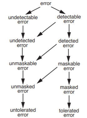
- A detectable error is one that can be detected reliably. If a detection procedure is in place and the error occurs, the system discovers it with near certainty and it becomes a detected error.
- A maskable error is one for which it is possible to devise a procedure to recover correctness. If a masking procedure is in place and the error occurs, is detected, and is masked, the error is said to be tolerated.
- Conversely, an untolerated error is one that is undetectable, undetected, unmaskable, or unmasked.
An untolerated error usually leads to a failure of the system. ("Usually," because we could get lucky and still produce a correct output, either because the error values didn’t actually matter under the current conditions, or some measure intended to mask a different error incidentally masks this one, too.) This classification of errors is illustrated in Figure \(\PageIndex{1}\).
.png?revision=1)
Figure \(\PageIndex{1}\): Classification of errors. Arrows lead from a category to mutually exclusive subcategories. For example, unmasked errors include both unmaskable errors and maskable errors that the designer decides not to mask.
A subtle consequence of the concept of a maskable error is that there must be a well-defined boundary around that part of the system state that might be in error. The masking procedure must restore all of that erroneous state to correctness, using information that has not been corrupted by the error. The real meaning of detectable, then, is that the error is discovered before its consequences have propagated beyond some specified boundary. The designer usually chooses this boundary to coincide with that of some module, and designs that module to be fail-fast (that is, it detects and reports its own errors). The system of which the module is a component then becomes responsible for masking the failure of the module.
Fault Tolerance Models
The distinctions among detectable, detected, maskable, and tolerated errors allow us to specify for a system a fault tolerance model, one of the components of the fault tolerance design process described in Section 2.2.2, as follows:
- Analyze the system and categorize possible error events into those that can be reliably detected and those that cannot. At this stage, detectable or not, all errors are untolerated.
- For each undetectable error, evaluate the probability of its occurrence. If that probability is not negligible, modify the system design in whatever way necessary to make the error reliably detectable.
- For each detectable error, implement a detection procedure and reclassify the module in which it is detected as fail-fast.
- For each detectable error try to devise a way of masking it. If there is a way, reclassify this error as a maskable error.
- For each maskable error, evaluate its probability of occurrence, the cost of failure, and the cost of the masking method devised in the previous step. If the evaluation indicates it is worthwhile, implement the masking method and reclassify this error as a tolerated error.
When finished developing such a model, the designer should have a useful fault tolerance specification for the system. Some errors, which have negligible probability of occurrence or for which a masking measure would be too expensive, are identified as untolerated. When those errors occur the system fails, leaving its users to cope with the result. Other errors have specified recovery algorithms, and when those occur the system should continue to run correctly. A review of the system recovery strategy can now focus separately on two distinct questions:
- Is the designer's list of potential error events complete, and is the assessment of the probability of each error realistic?
- Is the designer's set of algorithms, procedures, and implementations that are supposed to detect and mask the anticipated errors complete and correct?
These two questions are different. The first is a question of models of the real world. It addresses an issue of experience and judgment about real-world probabilities and whether all real-world modes of failure have been discovered or some have gone unnoticed. Two different engineers, with different real-world experiences, may reasonably disagree on such judgments—they may have different models of the real world. The evaluation of modes of failure and of probabilities is a point at which a designer may easily go astray because such judgments must be based not on theory but on experience in the field, either personally acquired by the designer or learned from the experience of others. A new technology, or an old technology placed in a new environment, is likely to create surprises. A wrong judgment can lead to wasted effort devising detection and masking algorithms that will rarely be invoked rather than the ones that are really needed. On the other hand, if the needed experience is not available, all is not lost: the iteration part of the design process is explicitly intended to provide that experience.
The second question is more abstract and also more absolutely answerable, in that an argument for correctness (unless it is hopelessly complicated) or a counterexample to that argument should be something that everyone can agree on. In system design, it is helpful to follow design procedures that distinctly separate these classes of questions. When someone questions a reliability feature, the designer can first ask, “Are you questioning the correctness of my recovery algorithm or are you questioning my model of what may fail?” and thereby properly focus the discussion or argument.
Creating a fault tolerance model also lays the groundwork for the iteration part of the fault tolerance design process. If a system in the field begins to fail more often than expected, or completely unexpected failures occur, analysis of those failures can be compared with the fault tolerance model to discover what has gone wrong. By again asking the two questions marked with bullets above, the model allows the designer to distinguish between, on the one hand, failure probability predictions being proven wrong by field experience, and on the other, inadequate or misimplemented masking procedures. With this information, the designer can work out appropriate adjustments to the model and the corresponding changes needed for the system.
Iteration and review of fault tolerance models is also important to keep them up to date in the light of technology changes. For example, the Network File System discussed in Section 1.10.1 was first deployed using a local area network, where packet loss errors are rare and may even be masked by the link layer. When later users deployed it on larger networks, where lost packets are more common, it became necessary to revise its fault tolerance model and add additional error detection in the form of end-to-end checksums. The processor time required to calculate and check those checksums caused some performance loss, which is why its designers did not originally include checksums. But loss of data integrity outweighed loss of performance and the designers reversed the trade-off.
To illustrate, an example of a fault tolerance model applied to a popular kind of memory devices, RAM, appears in Section 2.8. This fault tolerance model employs error detection and masking techniques that are described first in Section 2.5, so the reader may prefer to delay detailed study of that section until completing Section 2.5.