Piezoelectricity
- Page ID
- 322
\( \newcommand{\vecs}[1]{\overset { \scriptstyle \rightharpoonup} {\mathbf{#1}} } \)
\( \newcommand{\vecd}[1]{\overset{-\!-\!\rightharpoonup}{\vphantom{a}\smash {#1}}} \)
\( \newcommand{\dsum}{\displaystyle\sum\limits} \)
\( \newcommand{\dint}{\displaystyle\int\limits} \)
\( \newcommand{\dlim}{\displaystyle\lim\limits} \)
\( \newcommand{\id}{\mathrm{id}}\) \( \newcommand{\Span}{\mathrm{span}}\)
( \newcommand{\kernel}{\mathrm{null}\,}\) \( \newcommand{\range}{\mathrm{range}\,}\)
\( \newcommand{\RealPart}{\mathrm{Re}}\) \( \newcommand{\ImaginaryPart}{\mathrm{Im}}\)
\( \newcommand{\Argument}{\mathrm{Arg}}\) \( \newcommand{\norm}[1]{\| #1 \|}\)
\( \newcommand{\inner}[2]{\langle #1, #2 \rangle}\)
\( \newcommand{\Span}{\mathrm{span}}\)
\( \newcommand{\id}{\mathrm{id}}\)
\( \newcommand{\Span}{\mathrm{span}}\)
\( \newcommand{\kernel}{\mathrm{null}\,}\)
\( \newcommand{\range}{\mathrm{range}\,}\)
\( \newcommand{\RealPart}{\mathrm{Re}}\)
\( \newcommand{\ImaginaryPart}{\mathrm{Im}}\)
\( \newcommand{\Argument}{\mathrm{Arg}}\)
\( \newcommand{\norm}[1]{\| #1 \|}\)
\( \newcommand{\inner}[2]{\langle #1, #2 \rangle}\)
\( \newcommand{\Span}{\mathrm{span}}\) \( \newcommand{\AA}{\unicode[.8,0]{x212B}}\)
\( \newcommand{\vectorA}[1]{\vec{#1}} % arrow\)
\( \newcommand{\vectorAt}[1]{\vec{\text{#1}}} % arrow\)
\( \newcommand{\vectorB}[1]{\overset { \scriptstyle \rightharpoonup} {\mathbf{#1}} } \)
\( \newcommand{\vectorC}[1]{\textbf{#1}} \)
\( \newcommand{\vectorD}[1]{\overrightarrow{#1}} \)
\( \newcommand{\vectorDt}[1]{\overrightarrow{\text{#1}}} \)
\( \newcommand{\vectE}[1]{\overset{-\!-\!\rightharpoonup}{\vphantom{a}\smash{\mathbf {#1}}}} \)
\( \newcommand{\vecs}[1]{\overset { \scriptstyle \rightharpoonup} {\mathbf{#1}} } \)
\(\newcommand{\longvect}{\overrightarrow}\)
\( \newcommand{\vecd}[1]{\overset{-\!-\!\rightharpoonup}{\vphantom{a}\smash {#1}}} \)
\(\newcommand{\avec}{\mathbf a}\) \(\newcommand{\bvec}{\mathbf b}\) \(\newcommand{\cvec}{\mathbf c}\) \(\newcommand{\dvec}{\mathbf d}\) \(\newcommand{\dtil}{\widetilde{\mathbf d}}\) \(\newcommand{\evec}{\mathbf e}\) \(\newcommand{\fvec}{\mathbf f}\) \(\newcommand{\nvec}{\mathbf n}\) \(\newcommand{\pvec}{\mathbf p}\) \(\newcommand{\qvec}{\mathbf q}\) \(\newcommand{\svec}{\mathbf s}\) \(\newcommand{\tvec}{\mathbf t}\) \(\newcommand{\uvec}{\mathbf u}\) \(\newcommand{\vvec}{\mathbf v}\) \(\newcommand{\wvec}{\mathbf w}\) \(\newcommand{\xvec}{\mathbf x}\) \(\newcommand{\yvec}{\mathbf y}\) \(\newcommand{\zvec}{\mathbf z}\) \(\newcommand{\rvec}{\mathbf r}\) \(\newcommand{\mvec}{\mathbf m}\) \(\newcommand{\zerovec}{\mathbf 0}\) \(\newcommand{\onevec}{\mathbf 1}\) \(\newcommand{\real}{\mathbb R}\) \(\newcommand{\twovec}[2]{\left[\begin{array}{r}#1 \\ #2 \end{array}\right]}\) \(\newcommand{\ctwovec}[2]{\left[\begin{array}{c}#1 \\ #2 \end{array}\right]}\) \(\newcommand{\threevec}[3]{\left[\begin{array}{r}#1 \\ #2 \\ #3 \end{array}\right]}\) \(\newcommand{\cthreevec}[3]{\left[\begin{array}{c}#1 \\ #2 \\ #3 \end{array}\right]}\) \(\newcommand{\fourvec}[4]{\left[\begin{array}{r}#1 \\ #2 \\ #3 \\ #4 \end{array}\right]}\) \(\newcommand{\cfourvec}[4]{\left[\begin{array}{c}#1 \\ #2 \\ #3 \\ #4 \end{array}\right]}\) \(\newcommand{\fivevec}[5]{\left[\begin{array}{r}#1 \\ #2 \\ #3 \\ #4 \\ #5 \\ \end{array}\right]}\) \(\newcommand{\cfivevec}[5]{\left[\begin{array}{c}#1 \\ #2 \\ #3 \\ #4 \\ #5 \\ \end{array}\right]}\) \(\newcommand{\mattwo}[4]{\left[\begin{array}{rr}#1 \amp #2 \\ #3 \amp #4 \\ \end{array}\right]}\) \(\newcommand{\laspan}[1]{\text{Span}\{#1\}}\) \(\newcommand{\bcal}{\cal B}\) \(\newcommand{\ccal}{\cal C}\) \(\newcommand{\scal}{\cal S}\) \(\newcommand{\wcal}{\cal W}\) \(\newcommand{\ecal}{\cal E}\) \(\newcommand{\coords}[2]{\left\{#1\right\}_{#2}}\) \(\newcommand{\gray}[1]{\color{gray}{#1}}\) \(\newcommand{\lgray}[1]{\color{lightgray}{#1}}\) \(\newcommand{\rank}{\operatorname{rank}}\) \(\newcommand{\row}{\text{Row}}\) \(\newcommand{\col}{\text{Col}}\) \(\renewcommand{\row}{\text{Row}}\) \(\newcommand{\nul}{\text{Nul}}\) \(\newcommand{\var}{\text{Var}}\) \(\newcommand{\corr}{\text{corr}}\) \(\newcommand{\len}[1]{\left|#1\right|}\) \(\newcommand{\bbar}{\overline{\bvec}}\) \(\newcommand{\bhat}{\widehat{\bvec}}\) \(\newcommand{\bperp}{\bvec^\perp}\) \(\newcommand{\xhat}{\widehat{\xvec}}\) \(\newcommand{\vhat}{\widehat{\vvec}}\) \(\newcommand{\uhat}{\widehat{\uvec}}\) \(\newcommand{\what}{\widehat{\wvec}}\) \(\newcommand{\Sighat}{\widehat{\Sigma}}\) \(\newcommand{\lt}{<}\) \(\newcommand{\gt}{>}\) \(\newcommand{\amp}{&}\) \(\definecolor{fillinmathshade}{gray}{0.9}\)Piezoelectricity is the effect of mechanical strain and electric fields on a material; mechanical strain on piezoelectric materials will produce a polarity in the material, and applying an electric field to a piezoelectric material will create strain within the material. When pressure is applied to a piezoelectric material, a dipole and net polarization are produced in the direction of the applied stress. Piezoelectricity has many applications in regards to electrical transducers and signal devices.
Introduction
Brothers Pierre and Jacques Curie published the first paper on the direct piezoelectric effect in 1880; they applied stresses to crystals without a center of symmetry, and observed a surface charge on these crystals. Piezoelectricity comes from a Greek word; "piezo" means "to press" or "push"; therefore, piezoelectricity is creating electricity by applying pressure. Gabriel Lippmann predicted a "reverse" piezoelectric effect, and the Curie brothers later verified that to be the converse piezoelectric effect. This eventually gave rise to the reversibility of the piezoelectric effect and its applications.
Center of Symmetry
Materials must not have a center of symmetry in order to act as piezoelectric materials. In a material with a center of symmetry, the center of masses of the positive and negative charges coincide at the center of symmetry with or without mechanical strain, keeping zero net polarization. In the case of piezoelectric materials, when stress is applied, the center of masses of the positive and negative ions change depending on the direction the stress is applied; a net polarization is produced, creating a voltage difference between the two surfaces of the crystal the stress is being applied on.
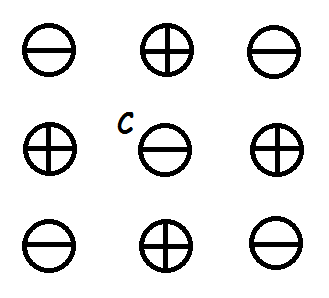
In Figure \(\PageIndex{1}\), no force is applied to the non-piezoelectric material; no polarization is induced, as the centers of mass for both the positive and negative ions coincide at point C.
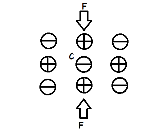
In Figure \(\PageIndex{2}\), a force is applied to the non-piezoelectric material; no polarization is induced, as the centers of mass for both the positive and negative ions still coincide at point C.
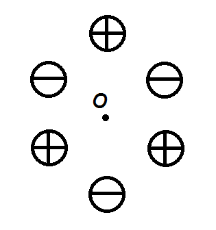
In Figure \(\PageIndex{3}\), a piezoelectric material is shown with no force applied to it. The centers of mass for both the positive and negative ions coincide at point O.
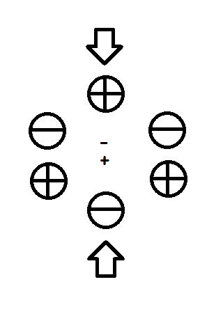
In Figure \(\PageIndex{4}\), when a vertical force is applied, the centers of mass for both the positive and negative ions shift, creating a net polarization as shown in the middle of the material. This process cancels out within the material until the ends of the material's surface.

In Figure \(\PageIndex{5}\), when a horizontal force is applied, the centers of mass for both the positive and negative ions still coincide with each other, producing no net polarization; a net polarization will be induced depending on the crystal structure, the direction the force is applied onto the material, and the material's Poisson ratio.
Mechanism
When a stress is applied to a piezoelectric material, the dimensions of the material changes. Depending on the direction the stress is applied, the resulting change in dimensions can shift the centers of mass for the positive and negative ions; this produces a dipole throughout the material. The dipoles inside the material cancel each other out, but on the surface of the material the dipoles are not canceled out, producing a polarity given by.
\[ P = d \ T = d \dfrac{F}{A} \nonumber\]
where T is the mechanical stress, P is the induced polarization, and d is the piezoelectric coefficient.
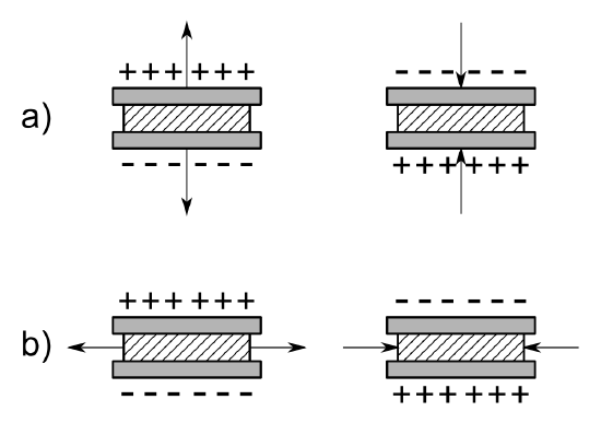
Polarization charge is given by
\[ P = \dfrac{Q}{A}\nonumber\]
where
- \(Q\) is the charge and
- \(A\) is the cross-sectional area of the piezoelectric material the stress is applied on.
The polarization induces a voltage due to the given by
\[ V = \dfrac {Q}{C} = \dfrac {A \ P}{\dfrac{\epsilon_{0}\epsilon_{r}A}{L}} = \dfrac{L \ P}{\epsilon_{0} \epsilon_{r}} = \dfrac{L (d \dfrac{F}{A})}{\epsilon_{0}\epsilon_{r}} = \dfrac {d \ L \ F}{\epsilon_{0}\epsilon_{r}A} \nonumber\]
where
- \(\epsilon_{0}\) is the vacuum permittivity,
- \(\epsilon_{r}\) is the relative permittivity,
- \(L\) is the length of the piezoelectric material, and
- \(C\) is the capacitance.
On the other hand, if an electric field is applied to the piezoelectric material, it produces a strain given by
\[ S = d \ E\nonumber\]
where \(E\) is the applied electric field, \(S\) is the produced strain, and d is the same piezoelectric coefficient as above. This is also known as the converse piezoelectric effect. In this case, negative ions would tend to move towards the positive end of the electric field, and the positive ions towards the negative end. As a result of the shift of the positive and negative ions, the dimensions of the material change, creating a strain within the material.
The piezoelectric coefficient is the same for both the direct and converse piezoelectric effect at the same magnitude of either electric field and induced strain or mechanical stress and induced polarization.
Poisson's ratio can also play a factor into piezoelectricity; if a piezoelectric material is compressed in one direction, it may expand in the other two directions. Poisson's ratio is given by
\[ \nu = -\dfrac{d\varepsilon_{trans}}{d\varepsilon_{axial}}\nonumber \]
where \(d\varepsilon_{trans}\) and \(d\varepsilon_{axial}\) are the strains in the two directions that were not compressed. An ideal piezoelectric material would have a Poisson ratio of 0, effectively removing its effect on the polarization.
Piezoelectric Materials
Piezoelectric materials require a lack of a center of symmetry. Out of the 21 crystal classes that have no center of symmetry The following 20 are able to produce a piezoelectric effect:
- 1, 2, m, 222, mm2, 4, 4, 422, 4 mm, 42m, 3, 32, 3m, 6, 6, 622, 6 mm, 62m, 23, 43m.
The only crystal class that has no piezoelectric effect is the 432 cubic class; the piezoelectric charges produced along its <111> axes cancel themselves out.
| Material | Use |
| Quartz (SiO2) | Crystal oscillators, ultrasonic transducers, delay lines, filters |
| Lead Zirconate Titanate, (PZT) | Earphones, Microphones, spark generators |
| Barium Titanate (BaTiO3) |
Accelerometers |
| Bismuth ferrite (BiFeO3) | Lead-free alternative |
Quartz's most common use is in watches and on radio stations on their respective wavelength,
\(PZT\)'s are ceramics created by powdering \(PbZrO_3\) and \(PbTiO_3\) and sintering them together by heating the powders up and letting them diffuse into each other, creating a composition of \(PbTi_{1-x}Zr_{x}O_3\) where x is usually 0.5. Though found in nature, it is usually mass-produced in labs. Due to the toxic nature of lead, lead-free alternatives are being researched.
Compound semiconductors also tend to exhibit piezoelectric effects.
Applications
Piezoelectricity plays a huge role in transducers; transducers convert different types of energy in another type of energy, in this case mechanical energy to electricity. In the case of microphones, the vibrations of the sound waves are converted into electric signals. Loudspeakers do the opposite, converting those electrical signals into sound waves. Piezoelectric transducers, rather than being used in audible wave ranges, find use on ultrasonic wave ranges.
Piezoelectric transducers are useful in ultrasonic wave applications. The Young's Modulus of a solid can be determined by finding the ultrasonic velocity of the wave traveling through the solid which is then converted to an electric signal read on an oscilloscope. lf there are cracks and defects within the material, the ultrasonic waves will either reflect or scatter; this allows for material failure analysis because the ultrasonic waves keep the material's structural integrity intact.
The Surface Acoustic Wave (SAW) device was produced primarily for its use as a filter; by interacting with the surface waves on circuit boards, one can either enhance or reduce certain frequencies produced by electric devices.
Other uses of piezoelectrics are transformers (to raise or lower electric voltages) and pressure sensors (using the piezoelectric effect to produce an electric response in the event of a pressure or frequency change).
Questions
- Do piezoelectric materials have a center of symmetry?
- What direction is the voltage produced by piezoelectricity?
- Transducers of piezoelectric materials convert what two types of energy?
Answers
- No.
- The direction of the applied electric field or mechanical stress.
- Mechanical and Electrical.
Additional Links
- Piezoelectricity (Wikipedia)
- Crystallographic point groups (Wikipedia)
- Transducers (Wikipedia)
-
References
- Sinclair, Ian. Sensors and Transducers. 3rd ed. Woburn, Massachusetts: Butterworth-Heinemann, 2001
- Kasap, Safa O. Principles of Electronic Materials and Devices. 3rd ed. Avenue of the Americas, New York: McGraw-Hill, 2005
- Arnau, Antonio. Piezoelectric Transducers and Applications. 2nd ed. Manhattan, New York: Springer, 2008
- Yang, Jiashi. An Introduction to the Theory of Piezoelectricity. Vol. 9. Manhattan, New York: Springer, 2005
Contributors
- Jack Lam

