19.8: Questions
- Page ID
- 31761
\( \newcommand{\vecs}[1]{\overset { \scriptstyle \rightharpoonup} {\mathbf{#1}} } \)
\( \newcommand{\vecd}[1]{\overset{-\!-\!\rightharpoonup}{\vphantom{a}\smash {#1}}} \)
\( \newcommand{\dsum}{\displaystyle\sum\limits} \)
\( \newcommand{\dint}{\displaystyle\int\limits} \)
\( \newcommand{\dlim}{\displaystyle\lim\limits} \)
\( \newcommand{\id}{\mathrm{id}}\) \( \newcommand{\Span}{\mathrm{span}}\)
( \newcommand{\kernel}{\mathrm{null}\,}\) \( \newcommand{\range}{\mathrm{range}\,}\)
\( \newcommand{\RealPart}{\mathrm{Re}}\) \( \newcommand{\ImaginaryPart}{\mathrm{Im}}\)
\( \newcommand{\Argument}{\mathrm{Arg}}\) \( \newcommand{\norm}[1]{\| #1 \|}\)
\( \newcommand{\inner}[2]{\langle #1, #2 \rangle}\)
\( \newcommand{\Span}{\mathrm{span}}\)
\( \newcommand{\id}{\mathrm{id}}\)
\( \newcommand{\Span}{\mathrm{span}}\)
\( \newcommand{\kernel}{\mathrm{null}\,}\)
\( \newcommand{\range}{\mathrm{range}\,}\)
\( \newcommand{\RealPart}{\mathrm{Re}}\)
\( \newcommand{\ImaginaryPart}{\mathrm{Im}}\)
\( \newcommand{\Argument}{\mathrm{Arg}}\)
\( \newcommand{\norm}[1]{\| #1 \|}\)
\( \newcommand{\inner}[2]{\langle #1, #2 \rangle}\)
\( \newcommand{\Span}{\mathrm{span}}\) \( \newcommand{\AA}{\unicode[.8,0]{x212B}}\)
\( \newcommand{\vectorA}[1]{\vec{#1}} % arrow\)
\( \newcommand{\vectorAt}[1]{\vec{\text{#1}}} % arrow\)
\( \newcommand{\vectorB}[1]{\overset { \scriptstyle \rightharpoonup} {\mathbf{#1}} } \)
\( \newcommand{\vectorC}[1]{\textbf{#1}} \)
\( \newcommand{\vectorD}[1]{\overrightarrow{#1}} \)
\( \newcommand{\vectorDt}[1]{\overrightarrow{\text{#1}}} \)
\( \newcommand{\vectE}[1]{\overset{-\!-\!\rightharpoonup}{\vphantom{a}\smash{\mathbf {#1}}}} \)
\( \newcommand{\vecs}[1]{\overset { \scriptstyle \rightharpoonup} {\mathbf{#1}} } \)
\(\newcommand{\longvect}{\overrightarrow}\)
\( \newcommand{\vecd}[1]{\overset{-\!-\!\rightharpoonup}{\vphantom{a}\smash {#1}}} \)
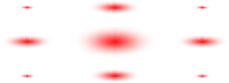
\(\newcommand{\avec}{\mathbf a}\) \(\newcommand{\bvec}{\mathbf b}\) \(\newcommand{\cvec}{\mathbf c}\) \(\newcommand{\dvec}{\mathbf d}\) \(\newcommand{\dtil}{\widetilde{\mathbf d}}\) \(\newcommand{\evec}{\mathbf e}\) \(\newcommand{\fvec}{\mathbf f}\) \(\newcommand{\nvec}{\mathbf n}\) \(\newcommand{\pvec}{\mathbf p}\) \(\newcommand{\qvec}{\mathbf q}\) \(\newcommand{\svec}{\mathbf s}\) \(\newcommand{\tvec}{\mathbf t}\) \(\newcommand{\uvec}{\mathbf u}\) \(\newcommand{\vvec}{\mathbf v}\) \(\newcommand{\wvec}{\mathbf w}\) \(\newcommand{\xvec}{\mathbf x}\) \(\newcommand{\yvec}{\mathbf y}\) \(\newcommand{\zvec}{\mathbf z}\) \(\newcommand{\rvec}{\mathbf r}\) \(\newcommand{\mvec}{\mathbf m}\) \(\newcommand{\zerovec}{\mathbf 0}\) \(\newcommand{\onevec}{\mathbf 1}\) \(\newcommand{\real}{\mathbb R}\) \(\newcommand{\twovec}[2]{\left[\begin{array}{r}#1 \\ #2 \end{array}\right]}\) \(\newcommand{\ctwovec}[2]{\left[\begin{array}{c}#1 \\ #2 \end{array}\right]}\) \(\newcommand{\threevec}[3]{\left[\begin{array}{r}#1 \\ #2 \\ #3 \end{array}\right]}\) \(\newcommand{\cthreevec}[3]{\left[\begin{array}{c}#1 \\ #2 \\ #3 \end{array}\right]}\) \(\newcommand{\fourvec}[4]{\left[\begin{array}{r}#1 \\ #2 \\ #3 \\ #4 \end{array}\right]}\) \(\newcommand{\cfourvec}[4]{\left[\begin{array}{c}#1 \\ #2 \\ #3 \\ #4 \end{array}\right]}\) \(\newcommand{\fivevec}[5]{\left[\begin{array}{r}#1 \\ #2 \\ #3 \\ #4 \\ #5 \\ \end{array}\right]}\) \(\newcommand{\cfivevec}[5]{\left[\begin{array}{c}#1 \\ #2 \\ #3 \\ #4 \\ #5 \\ \end{array}\right]}\) \(\newcommand{\mattwo}[4]{\left[\begin{array}{rr}#1 \amp #2 \\ #3 \amp #4 \\ \end{array}\right]}\) \(\newcommand{\laspan}[1]{\text{Span}\{#1\}}\) \(\newcommand{\bcal}{\cal B}\) \(\newcommand{\ccal}{\cal C}\) \(\newcommand{\scal}{\cal S}\) \(\newcommand{\wcal}{\cal W}\) \(\newcommand{\ecal}{\cal E}\) \(\newcommand{\coords}[2]{\left\{#1\right\}_{#2}}\) \(\newcommand{\gray}[1]{\color{gray}{#1}}\) \(\newcommand{\lgray}[1]{\color{lightgray}{#1}}\) \(\newcommand{\rank}{\operatorname{rank}}\) \(\newcommand{\row}{\text{Row}}\) \(\newcommand{\col}{\text{Col}}\) \(\renewcommand{\row}{\text{Row}}\) \(\newcommand{\nul}{\text{Nul}}\) \(\newcommand{\var}{\text{Var}}\) \(\newcommand{\corr}{\text{corr}}\) \(\newcommand{\len}[1]{\left|#1\right|}\) \(\newcommand{\bbar}{\overline{\bvec}}\) \(\newcommand{\bhat}{\widehat{\bvec}}\) \(\newcommand{\bperp}{\bvec^\perp}\) \(\newcommand{\xhat}{\widehat{\xvec}}\) \(\newcommand{\vhat}{\widehat{\vvec}}\) \(\newcommand{\uhat}{\widehat{\uvec}}\) \(\newcommand{\what}{\widehat{\wvec}}\) \(\newcommand{\Sighat}{\widehat{\Sigma}}\) \(\newcommand{\lt}{<}\) \(\newcommand{\gt}{>}\) \(\newcommand{\amp}{&}\) \(\definecolor{fillinmathshade}{gray}{0.9}\)Which of the masks below could have produced the following diffraction pattern?


- Answer
-
B will produce the diffraction pattern, since its dimensions correspond to the inverse relationship.
A's dimensions do not correspond to the inverse relationship.
C and D are cross-shaped apertures which will result in a more complex diffraction pattern.
Increasing the spread of the diffraction pattern allows for more accurate measurement of the spot spacing. Which one of these will achieve this?
- Hint: Take another look at Diffraction pattern formation.
- Answer
-
A is incorrect. The diffraction pattern visible in the back focal plane is smaller in size than the pattern produced on a screen without a lens.
B is incorrect. This will have no effect on the diffraction pattern (as long as the screen distance is unaffected).
C is incorrect. Red light has a longer wavelength, and hence the spot spacing will be smaller with blue light.
D is correct. This increases the screen distance, and hence the separation between the spots.
When the diffraction pattern from a particular grating is projected onto a screen, the even diffraction spots are missing, i.e. the second, fourth, etc. What is the relationship between the width of the slits (w) of the grating and the distance between each slit (s)?
- Answer
-
Diffraction pattern from a grating: the convolution theorem shows how the intensity function depends on the slit width and the slit spacing. The second maxima of the pattern (i.e. the second diffraction spot) lie 2λL/s on either side of the central position. The first minima of the binding sinc function lie at λL/w on either side of the central position. If these overlap, then all the even diffraction spots will be missing, due to the periodic nature of the pattern. Hence:
\[2 \lambda L / s=\lambda L / w\]
I.e.
\[s = 2w\]
The diffraction pattern from a single slit is projected onto a screen 0.90 m from the slit. Seven spots are visible, with a bright central spot. The maxima of the outer spots are a distance of 15 cm apart. A He-Ne laser is used, which produces light of a wavelength of 0.6328 μm. What is the width of the slit?
Hint: \(w=7 \frac{\lambda L}{x}\)
- Answer
-
From the diagram of the intensity pattern shown in the Diffraction 1 section it can be seen that the intensity is zero for
\[x=\frac{\lambda L}{w}, \frac{2 \lambda L}{w}\]
and so on. Outside the central bright spot, the other bright spots occur almost exactly half way between the zeros, i.e. close to
\[\frac{3}{2} \frac{\lambda L}{w}, \frac{5}{2} \frac{\lambda L}{w}, \frac{7}{2} \frac{\lambda L}{w}\]
Thus, if seven spots are visible, the distance x between the outermost pair on opposite sides of the central spot will be
\[2 \times \frac{7}{2} \frac{\lambda L}{w}\]
Hence the width of the slit w will be given by
\[7 \frac{\lambda L}{x}\]
Separation of outermost spots, x = 15 cm
Screen distance, L = 90 cm
Wavelength of diffracted light, λ = 0.6328 x 10⁻⁶ m
Therefore Slit width is\[w \approx 7\left(\frac{\lambda L}{x}\right)=\frac{7 \times 0.6328 \times 90}{15}=26.6 \mu \mathrm{m}\]
A convex lens has a focal length of 150 mm. If it is placed 180 mm from a mask on an optical bench, where must the screen be placed in order to focus the diffracted light into a sharp image?
- Answer
-
Object distance, u = 180 mm
Focal distance, f = 150 mmThe lens equation is
\[\frac{1}{u}+\frac{1}{v}=\frac{1}{f}\]
Therefore, image distance,
\[v=\left(\frac{1}{f}-\frac{1}{u}\right)^{-1}=\left(\frac{1}{150}-\frac{1}{180}\right)^{-1}=900 \mathrm{mm}\]
i.e. 1080 mm from the object.
As in the previous question, a convex lens has a focal length of 150 mm and is placed 180 mm from a mask on an optical bench. Where must the screen be placed in order to observe the diffraction pattern?
- Answer
-
The diffraction pattern can be observed at the back focal plane, located at the focal distance away from the lens, on the opposite side from the aperture, i.e. 150 mm from the lens, on the opposite side from the aperture.
As in the previous questions, a convex lens has a focal length of 150 mm and is placed 180 mm from a mask on an optical bench, giving an image distance of 900 mm. What is the magnification of the object in this set-up?
Hint: Magnification, m = v / u
- Answer
-
Image distance, v = 900 mm
Object distance, u = 180 mmTherefore, magnification
m = v / u = 900 / 180 = 5
As in the previous questions, a convex lens has a focal length of 150 mm and is placed 180 mm from a mask on an optical bench, giving an image distance of 900 mm. If the above lens is 56 mm in diameter, what is the finest grating size that could be resolved theoretically using light of wavelength 0.6328 μm?
Hint: In order to resolve the grating, the two first-order diffraction spots must be included in forming the image.
- Answer
-
Screen distance, L = 0.90 m
Pattern spacing, x = 0.5 x lens diameter = 28 mm (to include 2 diffracted spots)
Wavelength, λ = 0.6328 μmTherefore
\[s_{\min } H^{\prime \prime} \lambda L / x=0.6328 \times 10^{-6} \times 0.90 / 0.028=20.03 \mathrm{mm}\]
The theoretical resolution of a microscope is given by
\[d_{\min }=\frac{\lambda}{n \sin \alpha}\]
where n is the refractive index of the medium (n = 1 for air) and sinα is known as the numerical aperture, N.A. (commonly printed on the side of a lens). If a microscope can just resolve a "400 lines per mm" grating, what would the N.A. of the lens be?
- Answer
-
Resolution,
\[d_{\min }=\left(400 \mathrm{mm}^{-1}\right)^{-1}=2.5 \mathrm{mm}\]
Therefore, N.A.
\[\sin \alpha=\lambda\left(n d_{\min }\right)=0.6328 \times 10^{-6} /\left(1 \times 2.5 \times 10^{-6}\right)=0.253\]
A diffraction pattern shows just two-fold symmetry. Which one of these apertures could not have produced such a pattern?

- Answer
-
B. This aperture will produce a four-fold symmetry diffraction pattern, whereas the others will produce two-fold patterns. Diffraction patterns always have at least two-fold symmetry, even if the aperture has no symmetry. This can be seen mathematically in the nature of the Fourier Transform.
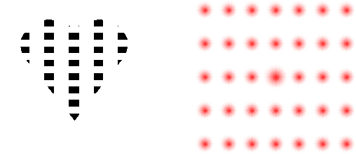
The following heart-shaped aperture produces the adjacent diffraction pattern.

Which of the following masks should be placed in the back focal plane in order to best study the horizontal stripes of the aperture in the image? Dashed lines are shown to identify location of central diffraction spot with respect to mask.

- Answer
-
C will be best. This will give a dark field image with respect to the horizontal stripes of the aperture, but with higher detail than B since more diffracted spots are going into making up the image.
A will give the bright field image in which the contrast of the strips will not be optimal.
B will give the dark field image with respect to the horizontal stripes of the aperture, with high contrast.
D will give a dark field image with respect to the vertical stripes of the aperture.


